conmoly 鑫聚新材
中文Request a Quote

CONMOLY / ENGINEERING & CONNECTIVITY

High-Voltage Power Feeder Cables

Reference configuration: High-voltage, wide-temperature, low-springback feeder paths for aircraft main power and electrification systems, controlling partial discharge, thermal aging, abrasion and constrained routing.

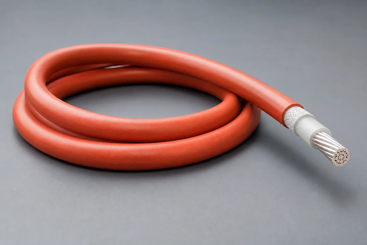
High-voltage aerospace power feeder cable construction
Product form illustration · Final construction depends on configuration

Power Enablers

CM-POWER-FEEDER

Power Feeder Cables

Reference configurations only; specifications and certifications require confirmation.

  • Reference · 1000 Vrms @ 25 kft
  • Reference · −65 to +260 °C
  • Reference · 3×OD bend radius

Reference specifications

Selection reference. Published third-party figures below describe specific reference configurations; they are not Conmoly guaranteed values or certifications. Confirm the final construction and test requirements with engineering.

Altitude, voltage and temperature values apply to their stated combinations and are not interchangeable as continuous ratings for arbitrary conditions.

Scroll the table horizontally to view all configuration conditions.

ParameterReference valueConfiguration / condition
Voltage rating1000 Vrms260 °C at 25 kft (7.6 km)
Voltage rating1850 Vrms260 °C at sea level
AC breakdown voltage> 15 kVTest value
Insulation resistance> 1 TΩAt 23 °C
Temperature / bend radius−65 to +260 °C · 3×ODMechanical/environmental range
Thermal endurance30,000 h @ 260 °CEndurance condition
Cut-through / abrasion> 800 N · > 1,000,000 cyclesMechanical tests

Reference source: www.gore.com

Available configurations

High-voltage single feederFor primary power distribution and high-current equipment.
Shielded feeder assemblyControls EMI and return path alongside high-voltage delivery.
Platform-specific feederGauge, length, terminals and routing form a complete assembly.

Cable construction

High-conductivity conductorGauge, stranding and plating are selected for resistance, flex and termination.
Primary insulationThin-wall high-temperature material establishes voltage, PD and abrasion margin.
Field or shield layerGrading, shielding and return paths are added for high-voltage or EMI needs.
Mechanical protectionTapes, braid or jacket improve cut-through, wear and installation durability.
Termination and strain reliefCrimp, solder, connector and thermal-cycle interfaces are controlled together.

Selection checklist

Voltage and currentContinuous/peak voltage, current, frequency and partial-discharge boundary
Gauge and dropLength, conductor section, resistance and allowable voltage drop
Thermal environmentAmbient, bundling, cooling and temperature rise
InstallationDiameter, mass, bend radius, vibration and abrasion
Material environmentFluids, humidity, flame, smoke/toxicity or vacuum
TerminationTerminal, crimp window, connector and strain relief

Applications

  • Rotorcraft and future vertical lift
  • eVTOL electrification
  • High-voltage airborne distribution
  • High-power equipment and actuators

Interfaces & termination

  • Pigtail, terminal or crimp-contact delivery
  • Single-, two- or multicore feeder construction
  • Shielded or unshielded complete assembly

Project validation checklist

  • Conductor resistance, voltage drop, hipot and insulation resistance
  • Partial discharge, breakdown and high-temperature electrical stability
  • Abrasion, cut-through, flex, tensile and vibration
  • Load temperature rise and post-cycle termination inspection

Ampacity, voltage and temperature rise must be defined with gauge, length, altitude, bundling, cooling and termination conditions.

High-Temperature Capacitor Films
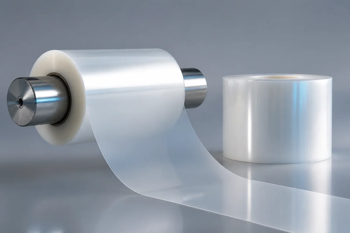
CM-POWER-FILM

High-Temperature Capacitor Films

Reference configuration: Low-loss engineered fluoropolymer film for aerospace power electronics and harsh-environment capacitors, maintaining voltage and capacitance stability under heat, field stress and long energized duty.

Reference · 4 μm filmReference · Low dielectric loss
View specifications
High-Performance Aerospace Wire
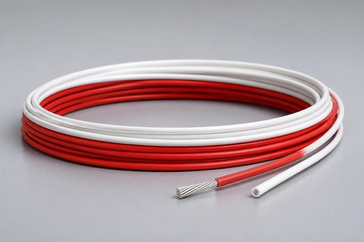
CM-POWER-HPW

High-Performance Aerospace Wire

Reference configuration: Temperature-resistant, chemically inert and abrasion-resistant engineered fluoropolymer insulation supports stable high-voltage, lightweight and long-term material reliability in current and next-generation aircraft electrical systems.

Reference · 600 Vrms directionReference · Stable PD behavior
View specifications
High-Temperature Magnet Wire
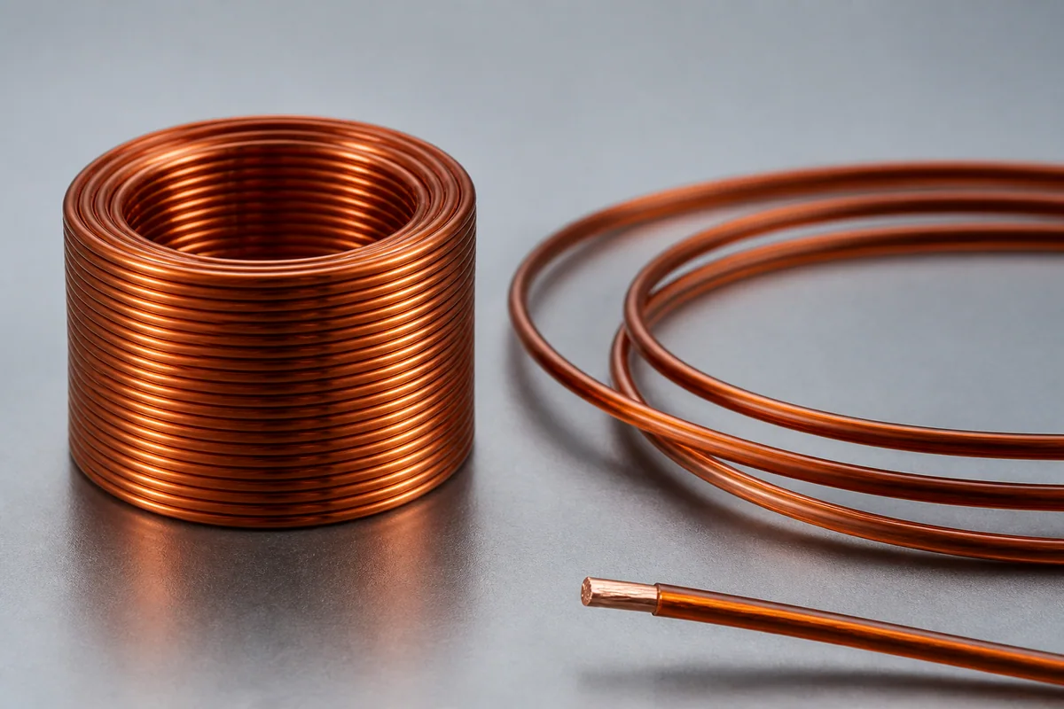
CM-POWER-MAGNET

High-Temperature Magnet Wire

Reference configuration: Engineered fluoropolymer insulation protects copper windings and maintains insulation resistance and breakdown performance in high temperature, high pressure, oil and hydrolysis environments.

Reference · 300–600 V ACReference · Up to 260 °C
View specifications