Fibre Channel copper · up to 1.625 GHz
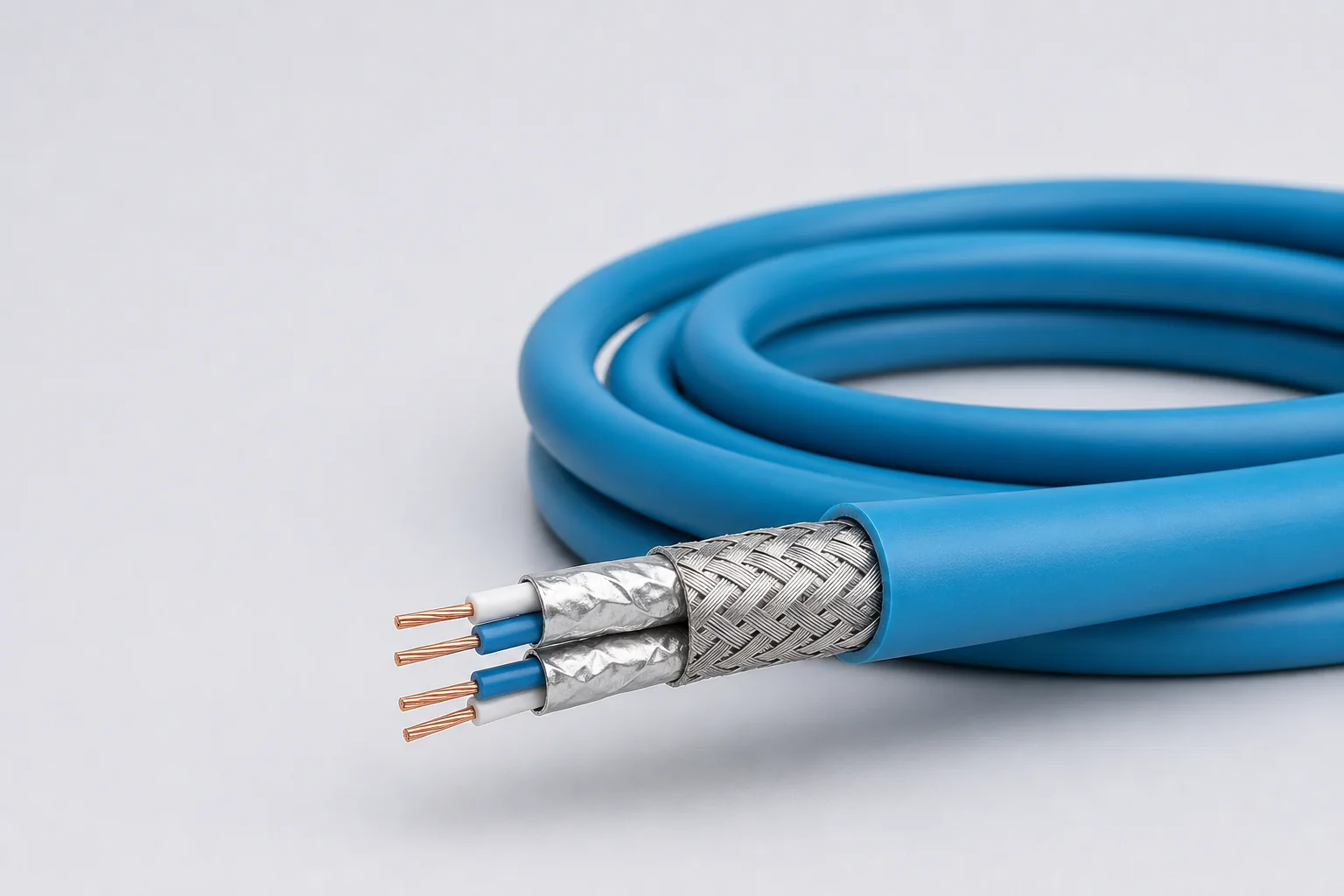
26 AWG dual differential pairs, overall shield and circular interface
150 ± 15 Ω · 3.0 ps/m intra-pair skew
Avionics enclosures and mission-computing equipment
Enquire about this configuration
CONMOLY / ENGINEERING & CONNECTIVITY
Reference configuration: 26 AWG, 150-ohm differential copper cable for reliable airborne and defense box-to-box links through 1.625 GHz, using 3.0 ps/m intra-pair skew and wide-temperature shielding to preserve serial-channel integrity.
Data Cables
CM-DATA-FC
Fibre Channel Cables
Reference configurations only; specifications and certifications require confirmation.
Selection reference. Published third-party figures below describe specific reference configurations; they are not Conmoly guaranteed values or certifications. Confirm the final construction and test requirements with engineering.
Values apply to the 26 AWG Fibre Channel copper construction.
Scroll the table horizontally to view all configuration conditions.
| Parameter | Reference value | Configuration / condition |
|---|---|---|
| Maximum transmission frequency | 1.625 GHz | Differential data link |
| Standard impedance | 150 ± 15 Ω | Nominal value |
| Typical operating voltage | < 15 V | System operating condition |
| Velocity / delay | 87% · 4.0 ns/m | Nominal values |
| Capacitance / intra-pair skew | 28.2 pF/m · 3.0 ps/m | Typical values |
| Dielectric withstand | 1500 / 1000 Vrms | Conductor-conductor / conductor-shield |
| Temperature range | −65 to +200 °C | FEP jacket |
Reference source: www.gore.com
| Box-to-box differential link | Two controlled-impedance copper paths provide transmit and receive connectivity between avionics enclosures. |
|---|---|
| Circular-connector assembly | Supports MIL-DTL-38999-style connectors and size-8 high-speed contact direction. |
| Compact DB-9 assembly | For small equipment interconnect, laboratory access and service testing. |
This family is Fibre Channel copper cable, not an optical-fiber jumper. Solution codes support early interface matching; final part number, length, connectors, shield termination and channel loss are confirmed to system requirements.
26 AWG dual differential pairs, overall shield and circular interface
150 ± 15 Ω · 3.0 ps/m intra-pair skew
Avionics enclosures and mission-computing equipment
Enquire about this configurationControlled-impedance copper cable with DB-9 termination
87% velocity · < 15 V
Small equipment, service testing and short box links
Enquire about this configurationConfigured by route, shield grounding and connectors
−65 to +200 °C · channel validation
Defense vehicles, storage equipment and custom airborne networks
Enquire about this configuration| Silver-plated copper-alloy conductors | Gauge, voltage drop, strength and termination contacts define the conductor construction. |
|---|---|
| Low-loss insulation | Expanded PTFE/PTFE controls impedance, delay and high-frequency attenuation. |
| Controlled signal units | Differential pairs, quads or multichannel video/data units are formed around the protocol. |
| Individual and overall shields | Pair coupling, external EMI and connector return continuity are managed together. |
| Environmental jacket | Wide temperature, abrasion, flame, marking and harness termination are balanced. |
| Protocol and speed | Interface revision, target rate, encoding and maximum channel length |
|---|---|
| Electrical boundary | Impedance, insertion/return loss, skew and dielectric withstand |
| Channel construction | Pair count, auxiliary wires, power and shield zoning |
| Installation envelope | Gauge, diameter, mass, bend radius and harness section |
| Environment | Temperature, vibration, abrasion, fluids, smoke/toxicity and flame |
| Termination | Connector, contact, backshell, grounding and strain relief |
Data rate and channel capability depend on the final cable, length, connectors and termination process and must be confirmed as a complete channel.
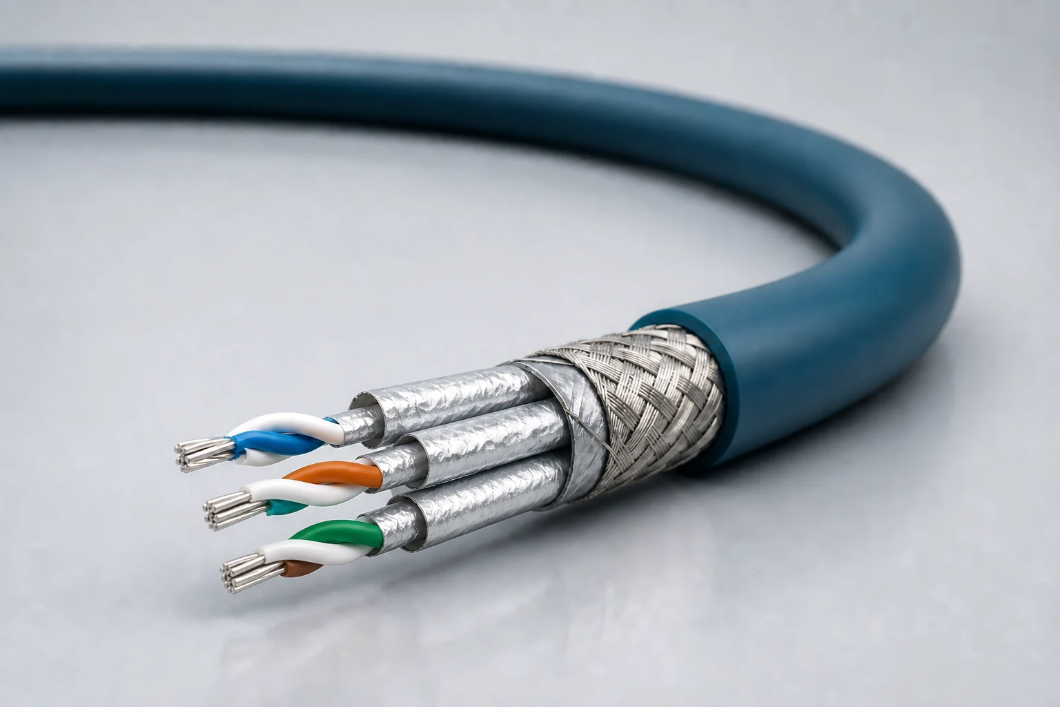
Reference configuration: Controlled-impedance interconnects for avionics, mission equipment, high-speed vision and precision industrial networks, spanning Cat 5e, Cat 6A and Cat 8 directions with insertion loss, return loss, crosstalk and skew managed as a complete channel.
View specifications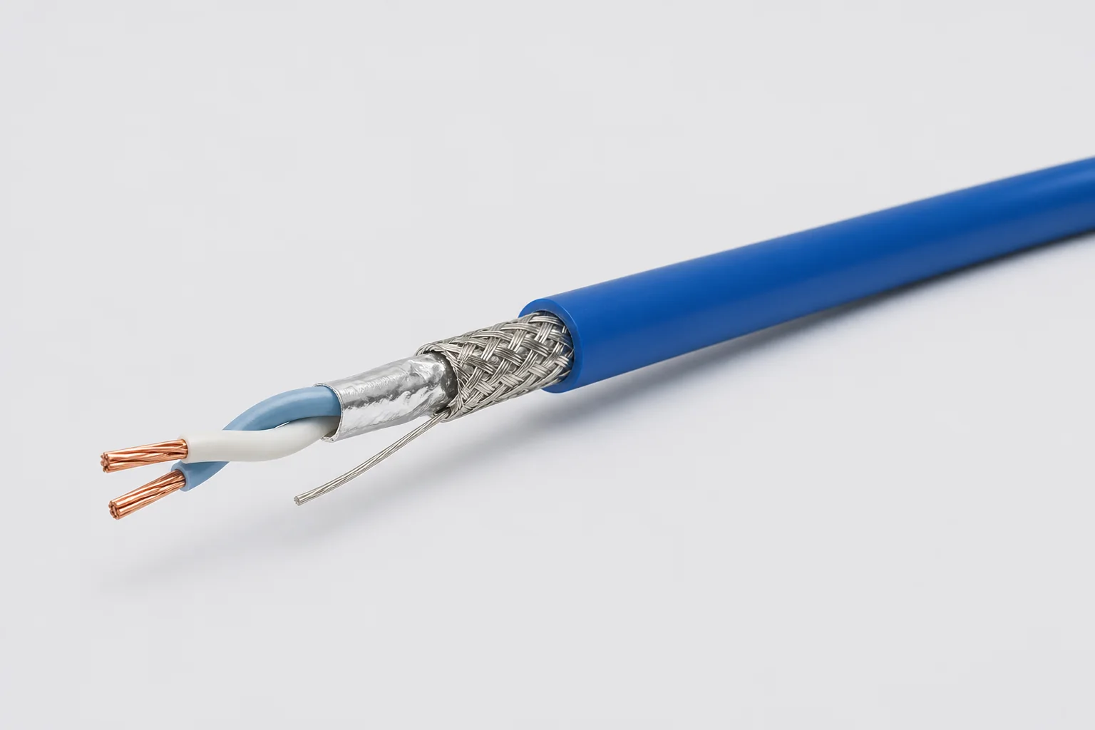
Reference configuration: 100-ohm single-pair shielded cable for aerospace, vehicle and precision-equipment differential links through 1 GHz, using controlled twist, foil, braid and drain paths to manage impedance, common-mode noise and wide-temperature reliability.
View specifications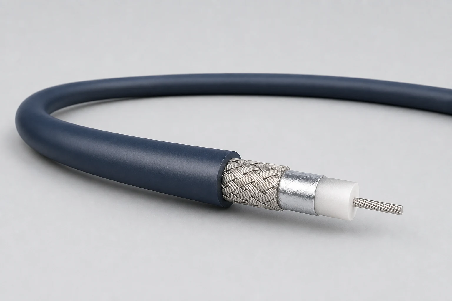
Reference configuration: Precision concentric transmission paths for video, timing, instrumentation and sensitive single-ended signals, spanning 50- and 75-ohm directions with frequency, loss, shielding and connector transitions defined as a complete assembly.
View specifications