Single-link DVI
24 AWG high-speed pairs plus auxiliary wires and composite shield
100 ± 10 Ω · pair-to-pair skew ≤ 52.50 ps/m
Cockpit displays, mission workstations and digital mapping
Enquire about this configuration
CONMOLY / ENGINEERING & CONNECTIVITY
Reference configuration: 24 AWG single-link digital-video interconnect for aerospace and defense displays, controlling its 100-ohm differential channel, insertion loss, pair-to-pair skew and intra-pair skew from −65 to +200 °C in demanding EMI environments.
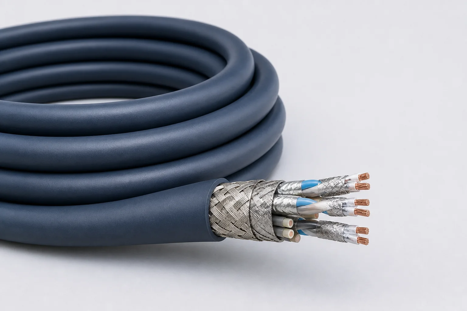
Data Cables
CM-DATA-DVI
DVI Cables
Reference configurations only; specifications and certifications require confirmation.
Selection reference. Published third-party figures below describe specific reference configurations; they are not Conmoly guaranteed values or certifications. Confirm the final construction and test requirements with engineering.
Values apply to the 24 AWG single-link digital-video construction.
Scroll the table horizontally to view all configuration conditions.
| Parameter | Reference value | Configuration / condition |
|---|---|---|
| Standard impedance | 100 ± 10 Ω | Differential channel |
| Typical operating voltage | < 15 V | Digital-video system |
| Velocity / delay | 80% · 4.07 ns/m | Nominal values |
| Capacitance | 40.0 pF/m | Nominal value |
| Pair-to-pair / intra-pair skew | 52.50 / 13.12 ps/m | Maximum values |
| Dielectric withstand | 1500 / 1000 Vrms | Conductor-conductor / conductor-shield |
| Temperature range | −65 to +200 °C | Engineered-fluoropolymer jacket |
Reference source: www.gore.com
| Single-link DVI cable | Carries the digital-video channel in a 24 AWG high-speed construction with controlled pair-to-pair and intra-pair skew. |
|---|---|
| Circular-connector assembly | Integrates video pairs, auxiliary conductors and shield continuity into airborne circular-connector termination. |
| Display-system harness | Defined around resolution, channel length, routing and platform EMI conditions. |
Solution codes support early interface, length and installation matching. Final part number, conductor definition, connector pinout, shield termination and complete-channel performance are confirmed in the drawing and technical specification.
24 AWG high-speed pairs plus auxiliary wires and composite shield
100 ± 10 Ω · pair-to-pair skew ≤ 52.50 ps/m
Cockpit displays, mission workstations and digital mapping
Enquire about this configurationControlled-impedance cable with airborne circular termination
−65 to +200 °C · < 15 V
Airborne equipment, vehicle displays and serviceable harnesses
Enquire about this configurationDefined by length, shield grounding and equipment interfaces
Intra-pair skew ≤ 13.12 ps/m · channel validation
Custom displays, image processing and high-EMI platforms
Enquire about this configuration| Silver-plated copper-alloy conductors | Gauge, voltage drop, strength and termination contacts define the conductor construction. |
|---|---|
| Low-loss insulation | Expanded PTFE/PTFE controls impedance, delay and high-frequency attenuation. |
| Controlled signal units | Differential pairs, quads or multichannel video/data units are formed around the protocol. |
| Individual and overall shields | Pair coupling, external EMI and connector return continuity are managed together. |
| Environmental jacket | Wide temperature, abrasion, flame, marking and harness termination are balanced. |
| Protocol and speed | Interface revision, target rate, encoding and maximum channel length |
|---|---|
| Electrical boundary | Impedance, insertion/return loss, skew and dielectric withstand |
| Channel construction | Pair count, auxiliary wires, power and shield zoning |
| Installation envelope | Gauge, diameter, mass, bend radius and harness section |
| Environment | Temperature, vibration, abrasion, fluids, smoke/toxicity and flame |
| Termination | Connector, contact, backshell, grounding and strain relief |
Data rate and channel capability depend on the final cable, length, connectors and termination process and must be confirmed as a complete channel.
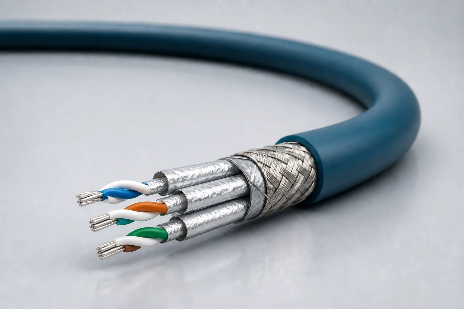
Reference configuration: Controlled-impedance interconnects for avionics, mission equipment, high-speed vision and precision industrial networks, spanning Cat 5e, Cat 6A and Cat 8 directions with insertion loss, return loss, crosstalk and skew managed as a complete channel.
View specifications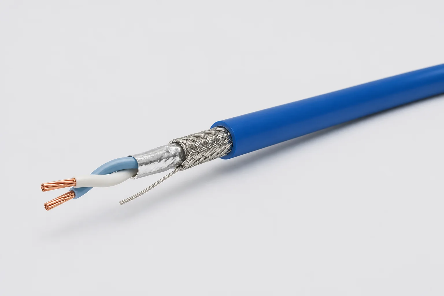
Reference configuration: 100-ohm single-pair shielded cable for aerospace, vehicle and precision-equipment differential links through 1 GHz, using controlled twist, foil, braid and drain paths to manage impedance, common-mode noise and wide-temperature reliability.
View specifications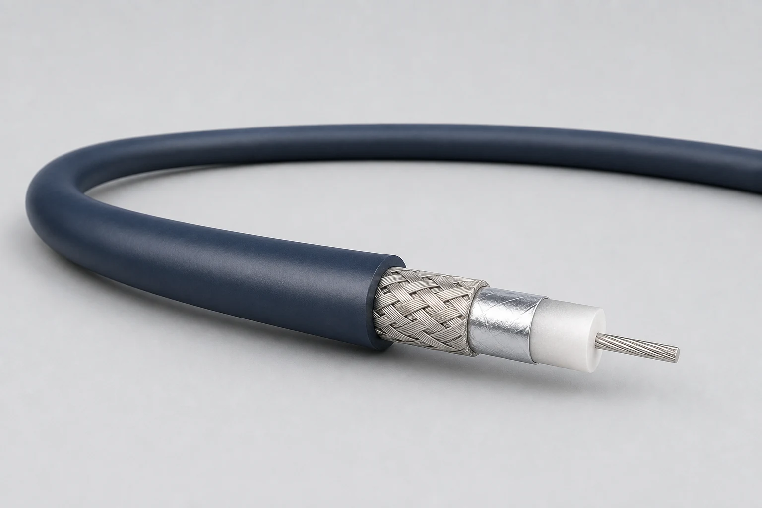
Reference configuration: Precision concentric transmission paths for video, timing, instrumentation and sensitive single-ended signals, spanning 50- and 75-ohm directions with frequency, loss, shielding and connector transitions defined as a complete assembly.
View specifications