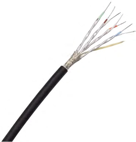
CM-CAT6A-4P
Cat 6A Ethernet Cables
Four-pair shielded Ethernet cables with ePTFE/PTFE insulation. Choose 24–30 AWG constructions to balance channel length, installation space and mass.
View specifications
CONMOLY / ENGINEERING & CONNECTIVITY
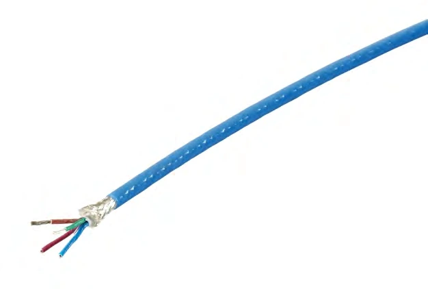
100-ohm, 24 AWG data-bus cable with low-density PTFE insulation and two shielding layers, for equipment networks and compact signal routing.
Data Cables
CM-GLINK-SQ
GLink Bus Cables
Available for project supply. Select a model below and confirm the order specification.
Catalogue data for available cable configurations. Final tolerances and acceptance requirements are agreed for the selected model.
Typical attenuation at +25 °C and sea level. Connector, link length and protocol compatibility are confirmed for the complete channel. The filler material and minimum installation bend radius are defined in the approved drawing.
Scroll the table horizontally to view all configuration conditions.
| Parameter | Catalogue value | Configuration / condition |
|---|---|---|
| Impedance | 100 Ω | Nominal |
| Capacitance | 44 pF/m | Listed model |
| Intra-pair skew | 15 ps/m | Listed model |
| Operating temperature | −65 to +200 °C | Finished cable, not dielectric material rating |
| Near-end crosstalk | ≥25 dB | 2500 MHz |
| Dielectric withstand | 1500 / 1000 V AC | Conductor–conductor / conductor–shield; duration to be agreed |
Cable Product Manual · A1 · PDF pages 29, 30
MODEL SELECTION
Scroll each table to compare all columns. Select a CM code to enquire about that model. A dash means no value is listed.
| Code | Conductor (AWG / stranding) | Core diameter (mm) | Shield diameter (mm) | Overall diameter (mm) | Mass (g/m) |
|---|---|---|---|---|---|
| CM-GLINK-SQ-AWG24 ↗ | 24 (19/35) | 1.15 | 3.4 | 3.8 | 32 |
| Frequency (MHz) | CM-GLINK-SQ-AWG24 |
|---|---|
| 312.5 | 0.4 |
| 500 | 0.52 |
| 625 | 0.58 |
| 750 | 0.64 |
| 1000 | 0.75 |
| 1250 | 0.86 |
| 2500 | 1.3 |
Cable Product Manual · A1 · PDF pages 29, 30
| GLink construction | CM-GLINK-SQ-AWG24 |
|---|
| Conductors | Silver-plated copper strands. |
|---|---|
| Insulation | ePTFE / PTFE; low-density PTFE separating tape. |
| Shield | Silver-plated copper tape and braided conductor layers. |
| Jacket | Fluoroplastic. |
| Signal and frequency | Protocol, frequency band, impedance and loss budget. |
|---|---|
| Installation | Length, routing, bend radius, motion and available space. |
| Environment | Operating temperature and required environmental tests. |
| Termination | Connector, pinout, shielding and strain relief. |
Catalogue values support selection. Final tolerances, assembly performance and acceptance tests are defined in the approved drawing and specification. No certification is implied.
Four-pair shielded Ethernet cables with ePTFE/PTFE insulation. Choose 24–30 AWG constructions to balance channel length, installation space and mass.
View specifications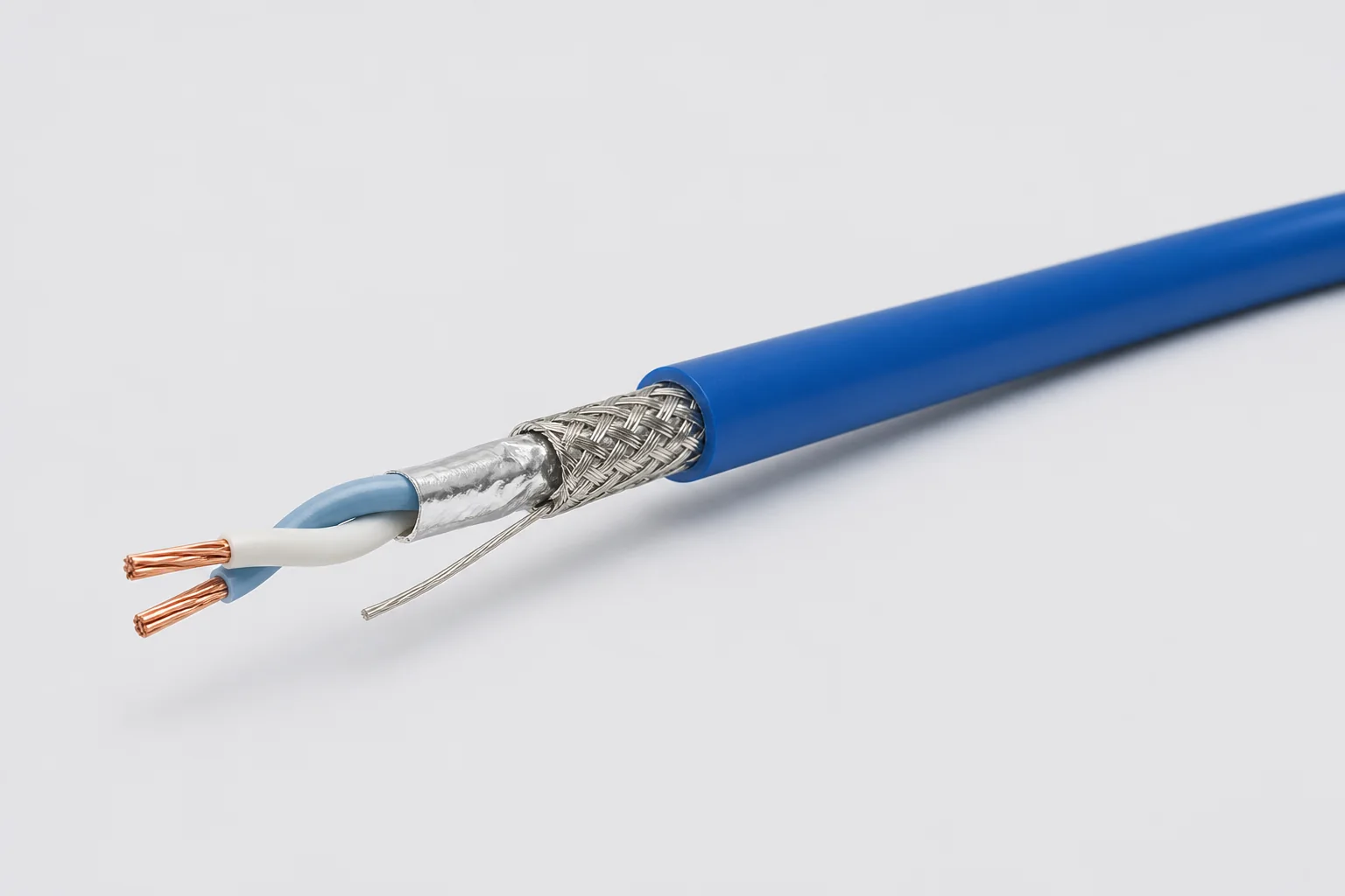
Reference configuration: 100-ohm single-pair shielded cable for aerospace, vehicle and precision-equipment differential links through 1 GHz, using controlled twist, foil, braid and drain paths to manage impedance, common-mode noise and wide-temperature reliability.
View specifications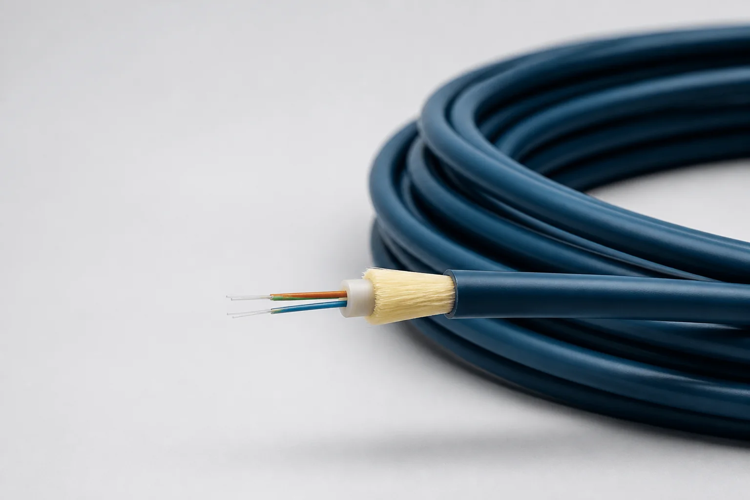
Reference configuration: Lightweight fiber-optic cable for aerospace and defense high-bandwidth interconnects, spanning singlemode and OM1–OM5 multimode directions through 100 Gb/s with PFA, FEP or PEEK jackets and buffered strength systems controlling optical loss, microbend and wide-temperature protection.
View specifications