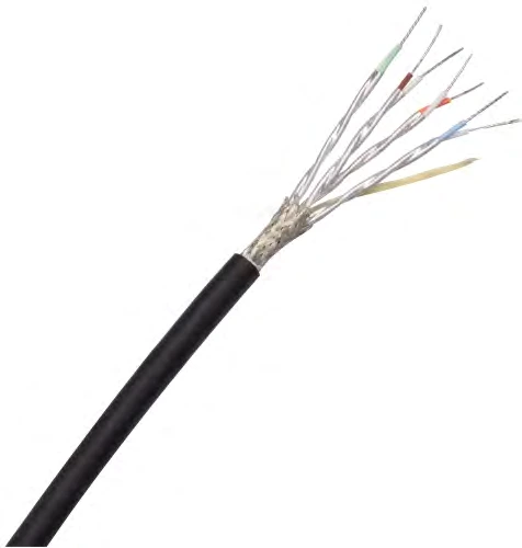
CM-CAT6A-4P
Cat 6A Ethernet Cables
Four-pair shielded Ethernet cables with ePTFE/PTFE insulation. Choose 24–30 AWG constructions to balance channel length, installation space and mass.
View specifications
CONMOLY / ENGINEERING & CONNECTIVITY
Shielded differential cables in twisted-pair and parallel-pair constructions. Compare 17 configurations by cross-section, delay, capacitance and frequency-dependent attenuation.
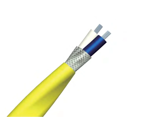
Data Cables
CM-LVDS
LVDS Differential Cables
Available for project supply. Select a model below and confirm the order specification.
Catalogue data for available cable configurations. Final tolerances and acceptance requirements are agreed for the selected model.
Typical attenuation at +25 °C and sea level. GHz values describe the listed cable cutoff frequency, not a guaranteed protocol data rate. Overall dimensions are width × height where two values are shown. Confirm connector strip dimensions and drain-wire construction before termination.
Scroll the table horizontally to view all configuration conditions.
| Parameter | Catalogue value | Configuration / condition |
|---|---|---|
| Nominal impedance | 100 Ω | Series overview: 100 ±10 Ω; final tolerance by drawing |
| Operating temperature | −55 to +150 °C | Series overview; confirm jacket and model |
| Dielectric withstand | 1500 / 1000 Vrms | Conductor–conductor / conductor–shield; duration to be agreed |
Cable Product Manual · A1 · PDF pages 31, 32, 33, 34, 35
MODEL SELECTION
Scroll each table to compare all columns. Select a CM code to enquire about that model. A dash means no value is listed.
| Code | Conductor (AWG / stranding) | Core dimensions (mm) | Drain wire | Overall dimensions (mm) | Mass (g/m) | Delay (ns/m) | Capacitance (pF/m) | Cutoff frequency (GHz) |
|---|---|---|---|---|---|---|---|---|
| CM-LVDS-TP-AWG28-S01 ↗ | 28 (7/36) | 0.98 | — | 2.10 × 1.70 | 10 | 4.5 | 45 | 1 |
| CM-LVDS-TP-AWG26-S01 ↗ | 26 (19/38) | 1.24 | — | 2.75 × 1.95 | 15 | 4.5 | 45 | 1 |
| CM-LVDS-TP-AWG24-S01 ↗ | 24 (7/32) | 1.6 | — | 3.20 × 2.50 | 20 | 4.25 | 43 | 1 |
| Frequency (MHz) | CM-LVDS-TP-AWG28-S01 | CM-LVDS-TP-AWG26-S01 | CM-LVDS-TP-AWG24-S01 |
|---|---|---|---|
| 20 | 0.18 | 0.16 | 0.1 |
| 100 | 0.4 | 0.3 | 0.22 |
| 200 | 0.6 | 0.42 | 0.31 |
| 500 | 0.9 | 0.7 | 0.52 |
| 1000 | 1.4 | 1.05 | 0.77 |
| Code | Conductor (AWG / stranding) | Core dimensions (mm) | Drain wire | Overall dimensions (mm) | Mass (g/m) | Delay (ns/m) | Capacitance (pF/m) | Cutoff frequency (GHz) |
|---|---|---|---|---|---|---|---|---|
| CM-LVDS-TP-AWG32-S01 ↗ | 32 (19/44) | 0.6 | 32 (19/44) | 1.35 × 0.90 | 2.7 | 4.1 | 41 | 5 |
| CM-LVDS-TP-AWG30-S01 ↗ | 30 (7/38) | 0.8 | 30 (7/38) | 1.80 × 1.35 | 4 | 4.2 | 37 | 5 |
| CM-LVDS-TP-AWG28-S02 ↗ | 28 (7/36) | 1 | 28 (7/36) | 2.25 × 1.45 | 6.8 | 4.2 | 37 | 5 |
| CM-LVDS-TP-AWG26-S02 ↗ | 26 (19/38) | 1.27 | 26 (19/38) | 2.70 × 1.80 | 9.5 | 4.2 | 37 | 5 |
| CM-LVDS-TP-AWG24-S02 ↗ | 24 (19/36) | 1.53 | 24 (19/36) | 3.40 × 2.10 | 13.5 | 4.2 | 37 | 5 |
| Frequency (MHz) | CM-LVDS-TP-AWG32-S01 | CM-LVDS-TP-AWG30-S01 | CM-LVDS-TP-AWG28-S02 | CM-LVDS-TP-AWG26-S02 | CM-LVDS-TP-AWG24-S02 |
|---|---|---|---|---|---|
| 200 | 0.85 | 0.55 | 0.45 | 0.35 | 0.3 |
| 600 | 1.45 | 1 | 0.85 | 0.65 | 0.55 |
| 1250 | 2.1 | 1.5 | 1.25 | 0.95 | 0.8 |
| 2500 | 2.95 | 2.1 | 1.7 | 1.35 | 1.15 |
| 3125 | 3.3 | 2.4 | 1.95 | 1.5 | 1.25 |
| 5000 | 4.3 | 3.1 | 2.6 | 2 | 1.7 |
| Code | Conductor (AWG / stranding) | Core dimensions (mm) | Drain wire | Overall dimensions (mm) | Mass (g/m) | Delay (ns/m) | Capacitance (pF/m) | Cutoff frequency (GHz) |
|---|---|---|---|---|---|---|---|---|
| CM-LVDS-PP-ND-AWG30-S01 ↗ | 30 (7/38) | 1.68 × 0.99 | — | 2.18 × 1.47 | 8 | 4.7 | 46 | 10 |
| CM-LVDS-PP-ND-AWG28-S01 ↗ | 28 (7/36) | 2.08 × 1.17 | — | 3.05 × 2.11 | 16 | 4.7 | 38 | 10 |
| CM-LVDS-PP-ND-AWG26-S01 ↗ | 26 (7/34) | 2.54 × 1.55 | — | 3.28 × 2.18 | 18 | 4.6 | 31 | 10 |
| CM-LVDS-PP-ND-AWG28-S02 ↗ | 28 (19/0.08 mm) | 1.95 × 1.15 | — | 2.50 × 1.83 | 12 | 4.1 | 36 | 7.5 |
| CM-LVDS-PP-ND-AWG26-S02 ↗ | 26 (19/0.10 mm) | 2.42 × 1.36 | — | 3.25 × 2.35 | 20 | 4.1 | 36 | 7.5 |
| CM-LVDS-PP-ND-AWG24-S01 ↗ | 24 (19/0.127 mm) | 3.10 × 1.75 | — | 3.95 × 2.65 | 26 | 4.1 | 36 | 7.5 |
| Frequency (GHz) | CM-LVDS-PP-ND-AWG30-S01 | CM-LVDS-PP-ND-AWG28-S01 | CM-LVDS-PP-ND-AWG26-S01 | CM-LVDS-PP-ND-AWG28-S02 | CM-LVDS-PP-ND-AWG26-S02 | CM-LVDS-PP-ND-AWG24-S01 |
|---|---|---|---|---|---|---|
| 0.5 | 1.15 | 0.75 | 0.65 | 0.65 | 0.55 | 0.45 |
| 1 | 1.65 | 1.15 | 0.95 | 0.95 | 0.75 | 0.6 |
| 2 | 2.45 | 1.65 | 1.5 | 1.45 | 1.2 | 0.85 |
| 5 | 4.2 | 2.9 | 2.65 | 2.1 | 1.9 | 1.5 |
| 7.5 | 5.45 | 4.9 | 4.65 | 2.8 | 2.5 | 2 |
| 10 | 7.9 | 6 | 5.6 | — | — | — |
| Code | Conductor (AWG / stranding) | Core dimensions (mm) | Drain wire | Overall dimensions (mm) | Mass (g/m) | Delay (ns/m) | Capacitance (pF/m) | Cutoff frequency (GHz) |
|---|---|---|---|---|---|---|---|---|
| CM-LVDS-PP-DW-AWG30-S01 ↗ | 30 (7/38) | 0.7 | 30 (7/38) | 1.75 × 1.15 | 4 | 4.2 | 40 | 10 |
| CM-LVDS-PP-DW-AWG28-S01 ↗ | 28 (19/40) | 1.1 | 28 (19/38) | 2.25 × 1.40 | 6 | 4.1 | 38 | 10 |
| CM-LVDS-PP-DW-AWG26-S01 ↗ | 26 (19/38) | 1.22 | 26 (19/36) | 2.70 × 1.70 | 8 | 4.1 | 38 | 10 |
| Frequency (GHz) | CM-LVDS-PP-DW-AWG30-S01 | CM-LVDS-PP-DW-AWG28-S01 | CM-LVDS-PP-DW-AWG26-S01 |
|---|---|---|---|
| 1 | 1.45 | 1.2 | 0.85 |
| 2 | 2.05 | 1.7 | 1.2 |
| 3 | 2.55 | 2.1 | 1.5 |
| 4 | 2.9 | 2.5 | 1.75 |
| 5 | 3.35 | 2.85 | 2.05 |
| 7 | 4.1 | 3.45 | 2.65 |
| 10 | 5.2 | 4.55 | 3.6 |
Cable Product Manual · A1 · PDF pages 31, 32, 33, 34, 35
| Twisted pair · 1 GHz | CM-LVDS-TP-AWG28-S01 · CM-LVDS-TP-AWG26-S01 · CM-LVDS-TP-AWG24-S01 |
|---|---|
| Twisted pair · 5 GHz | CM-LVDS-TP-AWG32-S01 · CM-LVDS-TP-AWG30-S01 · CM-LVDS-TP-AWG28-S02 · CM-LVDS-TP-AWG26-S02 · CM-LVDS-TP-AWG24-S02 |
| Parallel pair · without drain | CM-LVDS-PP-ND-AWG30-S01 · CM-LVDS-PP-ND-AWG28-S01 · CM-LVDS-PP-ND-AWG26-S01 · CM-LVDS-PP-ND-AWG28-S02 · CM-LVDS-PP-ND-AWG26-S02 · CM-LVDS-PP-ND-AWG24-S01 |
| Parallel pair · with drain | CM-LVDS-PP-DW-AWG30-S01 · CM-LVDS-PP-DW-AWG28-S01 · CM-LVDS-PP-DW-AWG26-S01 |
| Conductors | Silver-plated copper; gauge and stranding vary by model. |
|---|---|
| Insulation | ePTFE / PTFE. |
| Shield and drain | Braided conductor or aluminium composite tape; drain wire by construction. |
| Jacket | FEP; colour and final dimensions by model. |
| Signal and frequency | Protocol, frequency band, impedance and loss budget. |
|---|---|
| Installation | Length, routing, bend radius, motion and available space. |
| Environment | Operating temperature and required environmental tests. |
| Termination | Connector, pinout, shielding and strain relief. |
Catalogue values support selection. Final tolerances, assembly performance and acceptance tests are defined in the approved drawing and specification. No certification is implied.
Four-pair shielded Ethernet cables with ePTFE/PTFE insulation. Choose 24–30 AWG constructions to balance channel length, installation space and mass.
View specifications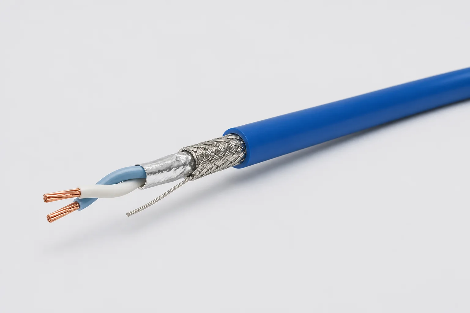
Reference configuration: 100-ohm single-pair shielded cable for aerospace, vehicle and precision-equipment differential links through 1 GHz, using controlled twist, foil, braid and drain paths to manage impedance, common-mode noise and wide-temperature reliability.
View specifications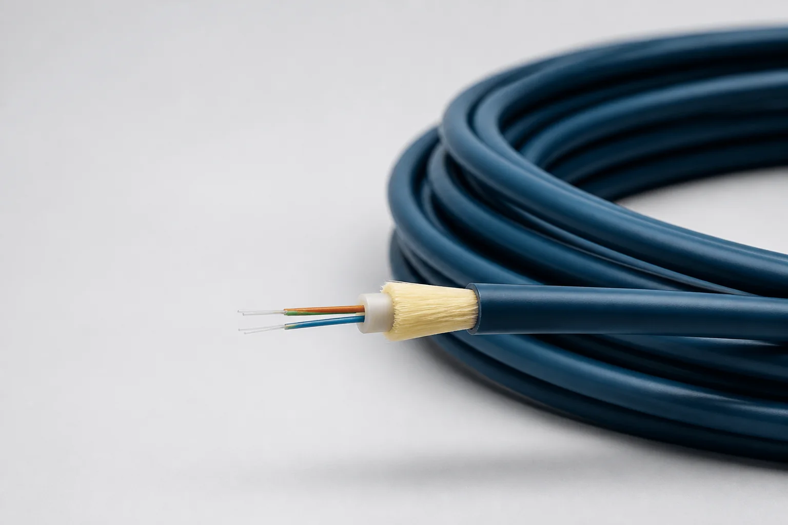
Reference configuration: Lightweight fiber-optic cable for aerospace and defense high-bandwidth interconnects, spanning singlemode and OM1–OM5 multimode directions through 100 Gb/s with PFA, FEP or PEEK jackets and buffered strength systems controlling optical loss, microbend and wide-temperature protection.
View specifications