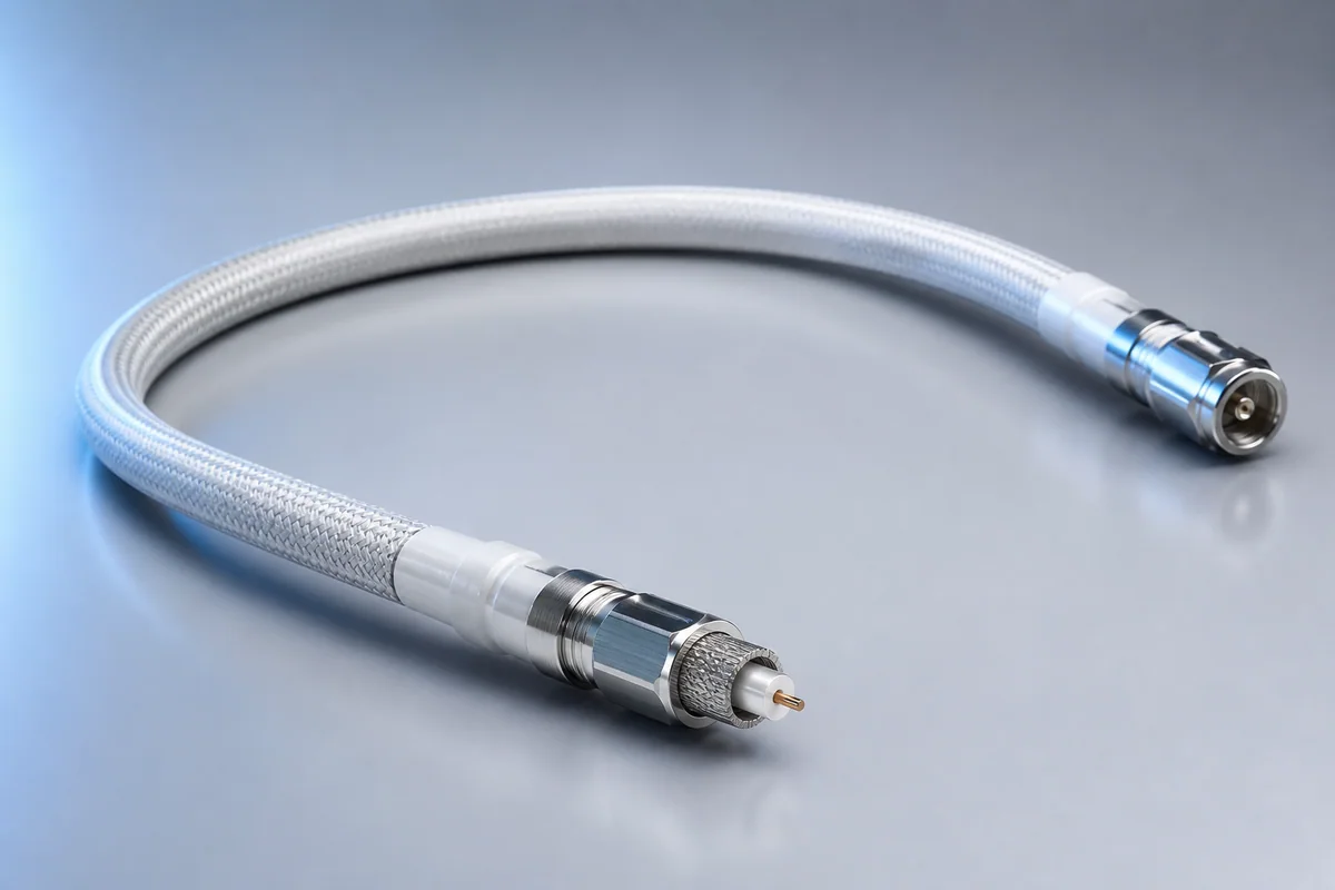
Reference configuration: Low-loss coax, lightweight shielding, low-profile connectors and thermomechanical ruggedization operate as one assembly to maintain signal integrity and phase stability through 40 GHz during launch and orbit.
Product form illustration · Final construction depends on configuration
Space Cables
CM-SPACE-RF
Spaceflight Microwave RF Assemblies
Reference configurations only; specifications and certifications require confirmation.
Selection reference. Published third-party figures below describe specific reference configurations; they are not Conmoly guaranteed values or certifications. Confirm the final construction and test requirements with engineering.
Frequency, insertion loss, diameter and connector vary by cable type; phase/time-delay matching is available by project.
Scroll the table horizontally to view all configuration conditions.
ESCC/NASA verification path for high-reliability missions.
NewSpace and launch assembly
Balances schedule, mass and mission environment validation.
High-power/high-density assembly
Frequency, diameter, power and connector are combined.
Cable construction
Space-grade conductor
Material, stranding and plating are selected for resistance, strength, flex and termination.
Low-outgassing insulation
Dielectric, thermal, vacuum-stability and processing requirements guide material selection.
Controlled functional unit
Single, twisted, shielded, coaxial or multicore signal geometry is formed.
Lightweight shield and cover
EMI, atomic oxygen, protection and mass are optimized together.
Termination and traceability
Connector, branch, strain relief, material lot and process records remain controlled.
Selection checklist
Mission and orbit
LEO, GEO, deep space, launch phase and mission duration
Electrical function
Voltage, current, protocol, frequency, impedance and core count
Mass and space
Mass per meter, diameter, bend radius and route
Environment
Vacuum, thermal cycle, radiation, ATOX, vibration and shock
Harness interface
Connector, branch, lacing, ground and installation process
Verification level
Applicable ESCC/NASA documents, first article, lot and traceability
Applications
Spaceborne antennas and payloads
Box-to-box and panel RF links
High-power/low-PIM equipment
LEO, GEO and deep-space missions
Interfaces & termination
Single, multicore or shielded space cable
Space connector and lightweight harness
Fixed-length assembly, branch or pigtail
Project validation checklist
Electrical baseline before and after thermal cycling
Vibration, shock, flex and termination retention
Mission-defined outgassing, radiation or atomic-oxygen evidence
First article, lot consistency and material/process traceability
Page values do not constitute mission qualification or approval. Applicable standards, lot screening and verification levels are confirmed per project.
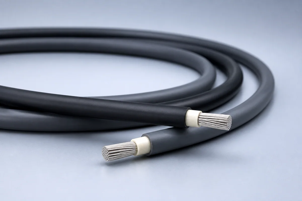
Reference configuration: Conductive or semi-conductive covers continuously drain static charge and provide lightweight, flexible, atomic-oxygen-resistant 600 Vrms power interconnects for moving LEO and GEO systems.
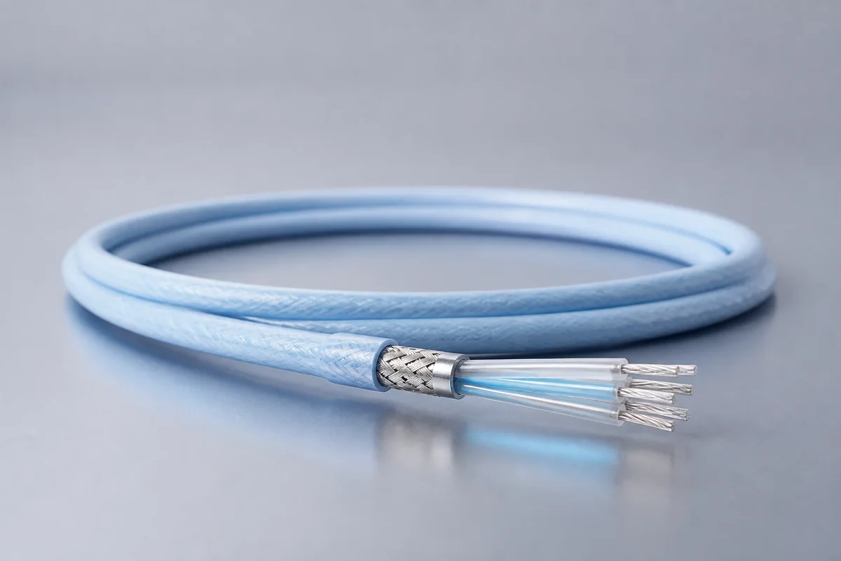
Reference configuration: ESCC 3901/025 lightweight GEO cable delivers 600 Vrms power and analog/low-frequency signals with smaller diameter, lower mass and tighter bending.
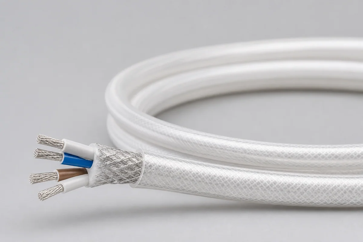
Reference configuration: ePTFE, PTFE and PFA combine in a chemical- and cut-through-resistant, low-springback wide-temperature space cable covering 12–30 AWG and multicore constructions.