conmoly 鑫聚新材
中文Request a Quote

CONMOLY / ENGINEERING & CONNECTIVITY

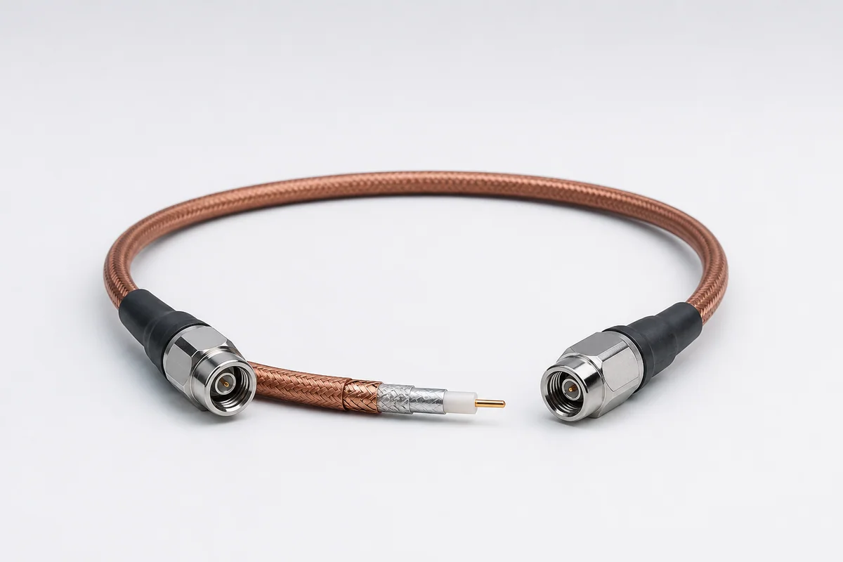
General-Purpose Microwave RF Assemblies

Reference configuration: Flexible low-loss RF interconnect direction for internal equipment, module-to-module, bench and environmental-test links, balancing compact routing, shielding and long-term amplitude/phase stability.

General-purpose microwave RF cable assembly
Product form illustration · Final construction depends on configuration

Microwave RF Cables & Assemblies

CM-RF-GENERAL

General Purpose

Reference configurations only; specifications and certifications require confirmation.

  • Reference · Flexible low-loss direction
  • Reference · Amplitude/phase stability
  • Reference · Multiple connector options

Reference specifications

Selection reference. Published third-party figures below describe specific reference configurations; they are not Conmoly guaranteed values or certifications. Confirm the final construction and test requirements with engineering.

Frequency, connector and standard length are combined by assembly family; final insertion loss and VSWR must be based on the selected assembly part number.

Scroll the table horizontally to view all configuration conditions.

ParameterReference valueConfiguration / condition
Maximum operating frequency70 GHzGeneral-purpose microwave/RF assembly family
Minimum bend radius2.54 mm (0.10 in)Applicable assembly configuration
Frequency families18 · 26.5 · 32 · 40 · 50 · 65 · 67 · 70 GHzSelected by assembly category
Standard lengths0.30 · 0.61 · 0.91 · 1.22 · 1.52 mCatalog standard configurations
Phase / time-delay matchingThrough 70 GHzSub-picosecond tolerances available
Connector optionsSMA · SMP · TNC-A · 2.92 mmConfigured by frequency and interface

Reference source: www.gore.com

Available configurations

Internal equipment interconnectFor board, module and enclosure paths with tight routing.
General test connectionFor repeat measurements on benches, load boards and automated test equipment.
Environmental-test connectionFor chamber, thermal-vacuum or remote-instrument paths where temperature and length change are evaluated.

Cable construction

Center conductorSize and finish selected for frequency, flex and termination.
Low-loss dielectricEstablishes target impedance and controls dielectric loss.
Outer conductorProvides return path, shielding and mechanical stability.
Protective jacketMatches bend, abrasion, temperature and chemical environment.
Precision connectorOptimized with transition, strain relief and assembly process.

Selection checklist

Frequency rangeMinimum/maximum frequency and critical test points
LengthAssembly length, tolerance and routing
Loss budgetAllowable insertion loss, return loss and shielding target
StabilityAmplitude/phase behavior with bend, temperature and time
MechanicalBend radius, motion, abrasion and strain relief
ConnectorSeries, gender, orientation and mounting

Applications

  • 5G and communication equipment test
  • Antenna arrays and clock distribution
  • ATE, load boards and evaluation boards
  • Module, enclosure and board interconnects

Interfaces & termination

  • Common precision coax connector directions
  • Straight, right-angle and panel-mount
  • Fixed-length or matched RF assemblies

Project validation checklist

  • S-parameters and shielding effectiveness
  • Amplitude/phase comparison with bend and temperature
  • Connector repeat mating and torque
  • Length, appearance, continuity and mechanical retention

Frequency, loss and stability values are supplied only after cable type, length, connector and test conditions are defined.

Ruggedized RF Test Assemblies
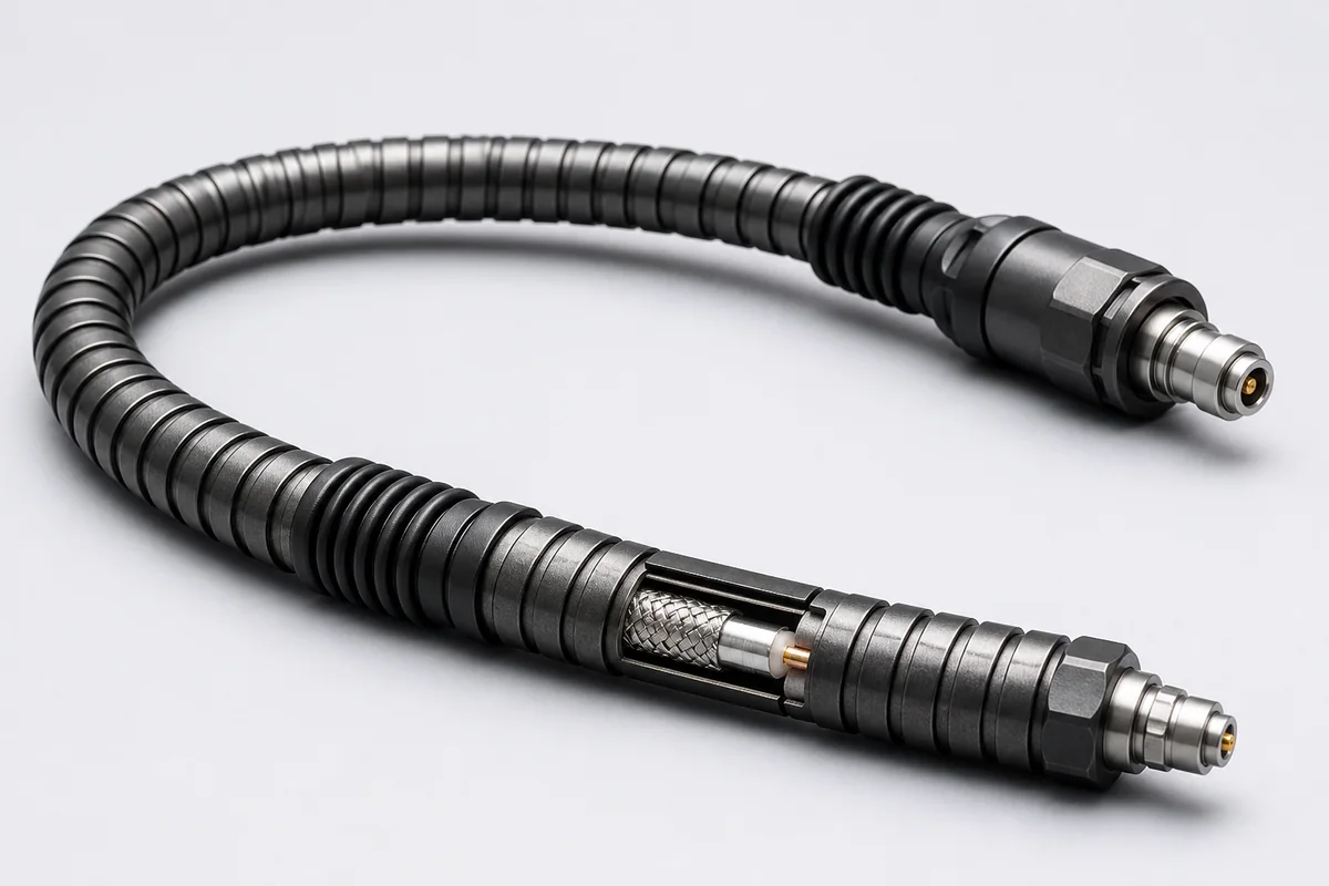
CM-RF-RUGGED-TEST

Ruggedized RF Test Assemblies

Reference configuration: Cable, connector and strain-relief systems reinforced for frequent flexing, mating, twisting and accidental mechanical loads in laboratories, production lines and field testing.

Reference · Crush and kink resistance directionReference · Repeatable measurement
View specifications
VNA RF Test Assemblies
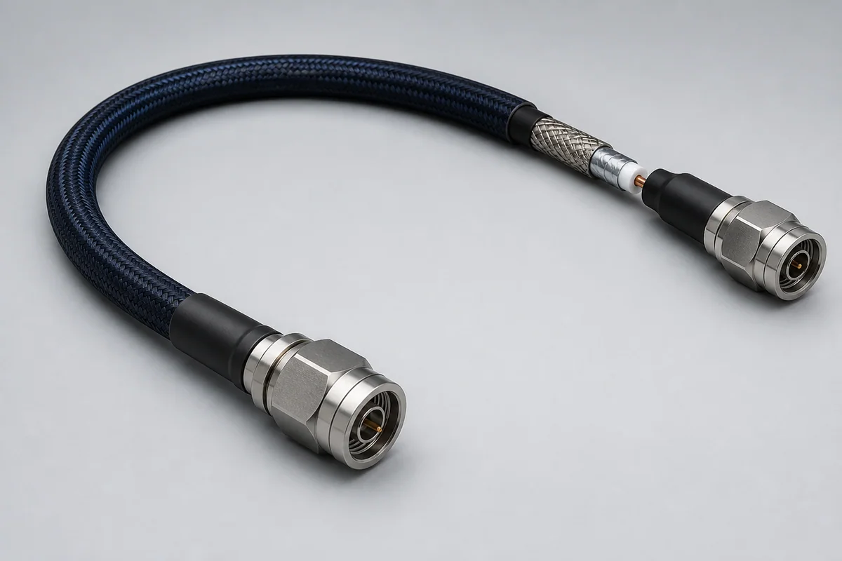
CM-RF-VNA

VNA RF Test Assemblies

Reference configuration: Precision vector-network-analyzer paths using low-springback flexible construction, precision connectors and controlled assembly to improve reconnect repeatability and measurement stability between calibrations.

Reference · Precision repeatabilityReference · Low-springback flexibility
View specifications
Ruggedized Airframe Microwave Assemblies
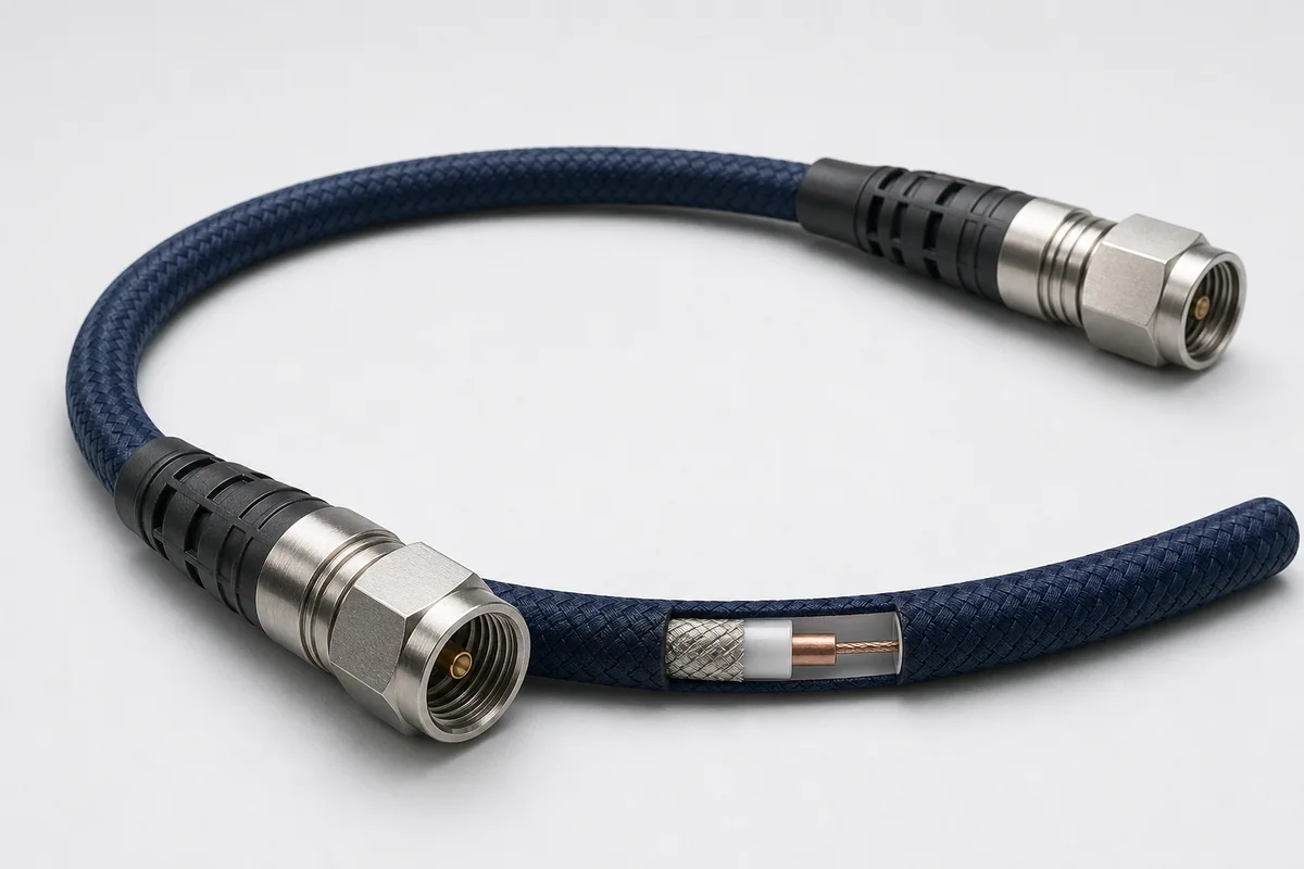
CM-RF-AIRFRAME

Ruggedized Airframe Microwave Assemblies

Reference configuration: Lightweight flexible 50-ohm RF assemblies for civil and military aircraft, maintaining link performance through 40 GHz across routing, maintenance, vibration and flight conditions.

Reference · Up to 40 GHzReference · >90 dB shielding

View specifications