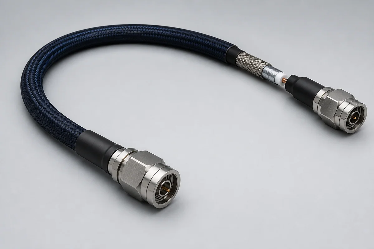
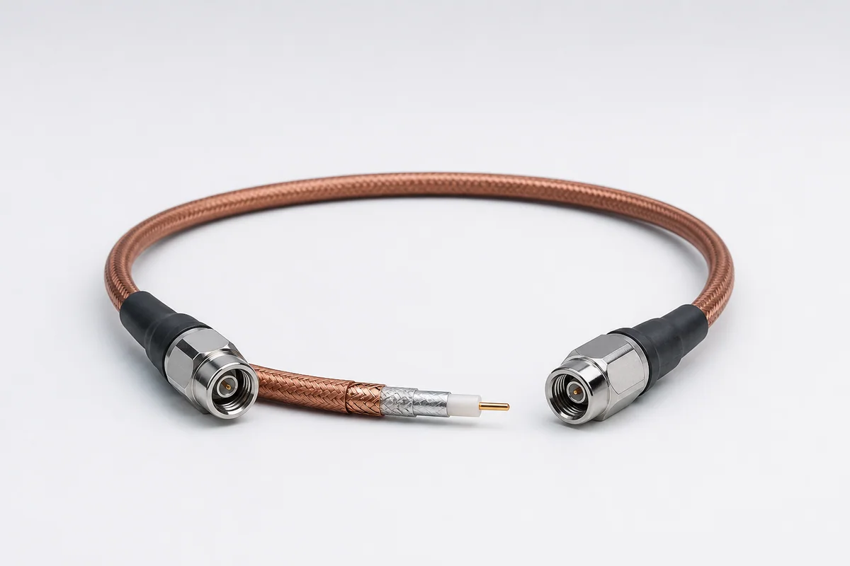
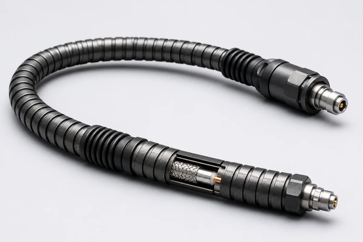
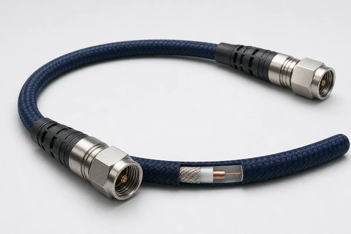
Reference configuration: Precision vector-network-analyzer paths using low-springback flexible construction, precision connectors and controlled assembly to improve reconnect repeatability and measurement stability between calibrations.
Product form illustration · Final construction depends on configuration
Microwave RF Cables & Assemblies
CM-RF-VNA
VNA
Reference configurations only; specifications and certifications require confirmation.
Selection reference. Published third-party figures below describe specific reference configurations; they are not Conmoly guaranteed values or certifications. Confirm the final construction and test requirements with engineering.
Different VNA assembly types cover 26.5–70 GHz; crush and flex-life values are listed against the applicable test conditions.
Scroll the table horizontally to view all configuration conditions.
Stable handling connection between a VNA port and device under test.
NMD-style rugged interface direction
For fast instrument-side adaptation and repeated connection; exact interface is confirmed from the analyzer.
Precision laboratory assembly
Length, connectors and handling rules defined for critical amplitude and S-parameter measurements.
Cable construction
Precision coax core
Controls impedance, insertion/return loss and electrical length.
Phase-stable structure
Reduces geometry and dielectric change from bend and temperature.
Crush/twist protection
Protects the measurement core from laboratory mechanical damage.
Low-springback jacket
Improves placement and reduces force applied to the DUT.
Instrument-grade connector
Controls interface geometry, torque and adapter boundary.
Selection checklist
VNA frequency
Analyzer port and target maximum frequency
Connector
Interface size, gender, NMD/conventional direction and adapters
Length
Reach, bend path and electrical-length requirement
Measurement
Insertion loss, return loss, phase, group delay or device behavior
Calibration
Reference plane, use frequency and allowable drift
Handling
Torque, mating, storage and minimum bend radius
Applications
VNA port extension
Device and material S-parameter measurement
Critical laboratory and calibration paths
Millimeter-wave module, antenna and package test
Interfaces & termination
Precision N, 7 mm, 3.5/2.92/2.4/1.85 mm directions
NMD-style analyzer interface direction
Male/female adapters and port protection
Project validation checklist
Full-band insertion loss, return loss and phase baseline
Measurement difference after repeated bend and reconnection
Temperature and time stability
Connector end face, torque, tensile and mechanical durability
Interfaces and frequency ranges are selection directions only; precision capability must be confirmed with the analyzer, calibration kit, adapters and complete uncertainty budget.
Reference configuration: Cable, connector and strain-relief systems reinforced for frequent flexing, mating, twisting and accidental mechanical loads in laboratories, production lines and field testing.
Reference · Crush and kink resistance directionReference · Repeatable measurement
Reference configuration: Lightweight flexible 50-ohm RF assemblies for civil and military aircraft, maintaining link performance through 40 GHz across routing, maintenance, vibration and flight conditions.
Reference · Up to 40 GHzReference · >90 dB shielding