conmoly 鑫聚新材
中文Request a Quote

CONMOLY / ENGINEERING & CONNECTIVITY

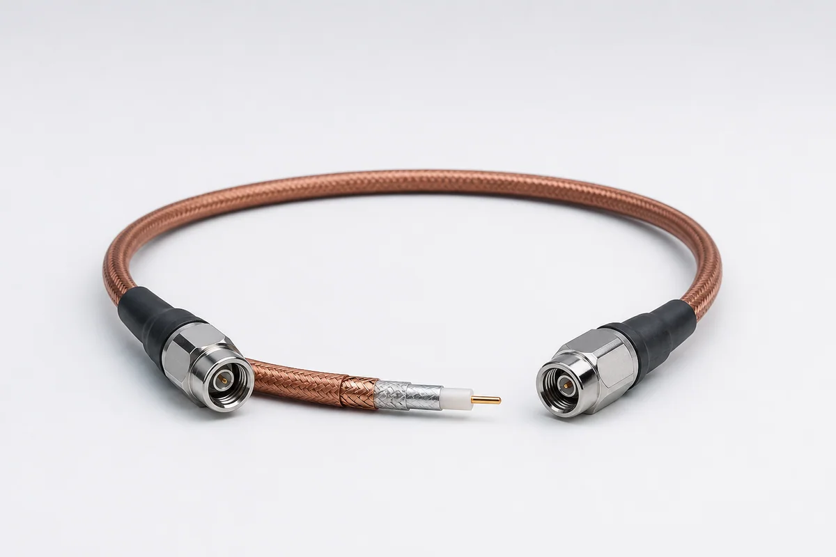
Vapor-Sealed Microwave RF Assemblies

Reference configuration: A durable barrier prevents water, vapor, fuel and aircraft contaminants from entering while maintaining low loss, phase stability and high shielding through 40 GHz.

Vapor-sealed microwave RF coaxial assembly construction
Product form illustration · Final construction depends on configuration

Microwave RF Cables & Assemblies

CM-RF-SEALED

Vapor Sealed

Reference configurations only; specifications and certifications require confirmation.

  • Reference · 2–40 GHz family
  • Reference · −58 to +200 °C
  • Reference · Vapor and fluid barrier

Reference specifications

Selection reference. Published third-party figures below describe specific reference configurations; they are not Conmoly guaranteed values or certifications. Confirm the final construction and test requirements with engineering.

Types 7G, 75, 7E, 7L and 7M cover different frequencies, diameters and bend radii.

Scroll the table horizontally to view all configuration conditions.

ParameterReference valueConfiguration / condition
Maximum frequency2–40 GHzBy cable type
Typical VSWR1.10:1–1.30:1At maximum frequency, straight connector
Typical insertion loss0.04–0.78 dB/ftAt each type's maximum frequency
Standard impedance / velocity50 ± 1 Ω · 85%Full family
Shielding effectiveness> 90 dBThrough each type's maximum frequency
Diameter / minimum bend radius3.80–14.35 / 19–80 mmBy cable type
Temperature / concentrated load−58 to +200 °C · 50 lb/inFull family

Reference source: www.gore.com

Available configurations

Types 7G / 75 / 7ECompact low-loss families spanning 18–40 GHz.
Types 7L / 7M2–7 GHz and larger power/diameter direction.
Replaceable-connector assemblyDefined around SMA, TNC and related interfaces and length.

Cable construction

Silver-plated center conductorSolid or stranded geometry is selected for frequency, power, flex and termination.
Expanded PTFE dielectricMaintains 50-ohm coaxial geometry while reducing high-frequency dielectric loss.
Multilayer outer conductorA stable return and shielding path limits impedance change after installation.
Rugged or barrier jacketResists crush, abrasion, bending, vapor and aircraft-fluid ingress.
Replaceable connectorInterface, direction, length and service strategy complete the assembly.

Selection checklist

Frequency and powerMaximum frequency, CW/pulse power and link loss
Amplitude and phaseVSWR, insertion loss, phase, delay and thermal stability
Assembly lengthEquipment spacing, service loop, route and matching
InstallationDiameter, mass, bend radius, crush and maintenance loads
EnvironmentTemperature, vibration, vapor, fuel, fluids and EMI
ConnectorSMA, TNC, 2.92 mm and replaceable-interface options

Applications

  • AESA radar
  • Electronic defense and signal detection
  • SATCOM and GPS
  • L-band air-to-ground communications

Interfaces & termination

  • SMA, TNC, 2.92 mm and related RF interfaces
  • Straight, right-angle and low-profile connectors
  • Fixed-length assembly and replaceable connector interface

Project validation checklist

  • Full-band insertion loss, return loss, VSWR and amplitude/phase
  • Comparison before and after installation bending, crush and connector fit
  • Thermal cycle, vibration, fluid or vapor-barrier tests
  • Repeated mating, tensile and torque retention

RF values vary by cable type, frequency, length and connector. The finished assembly must be tested in its defined configuration.

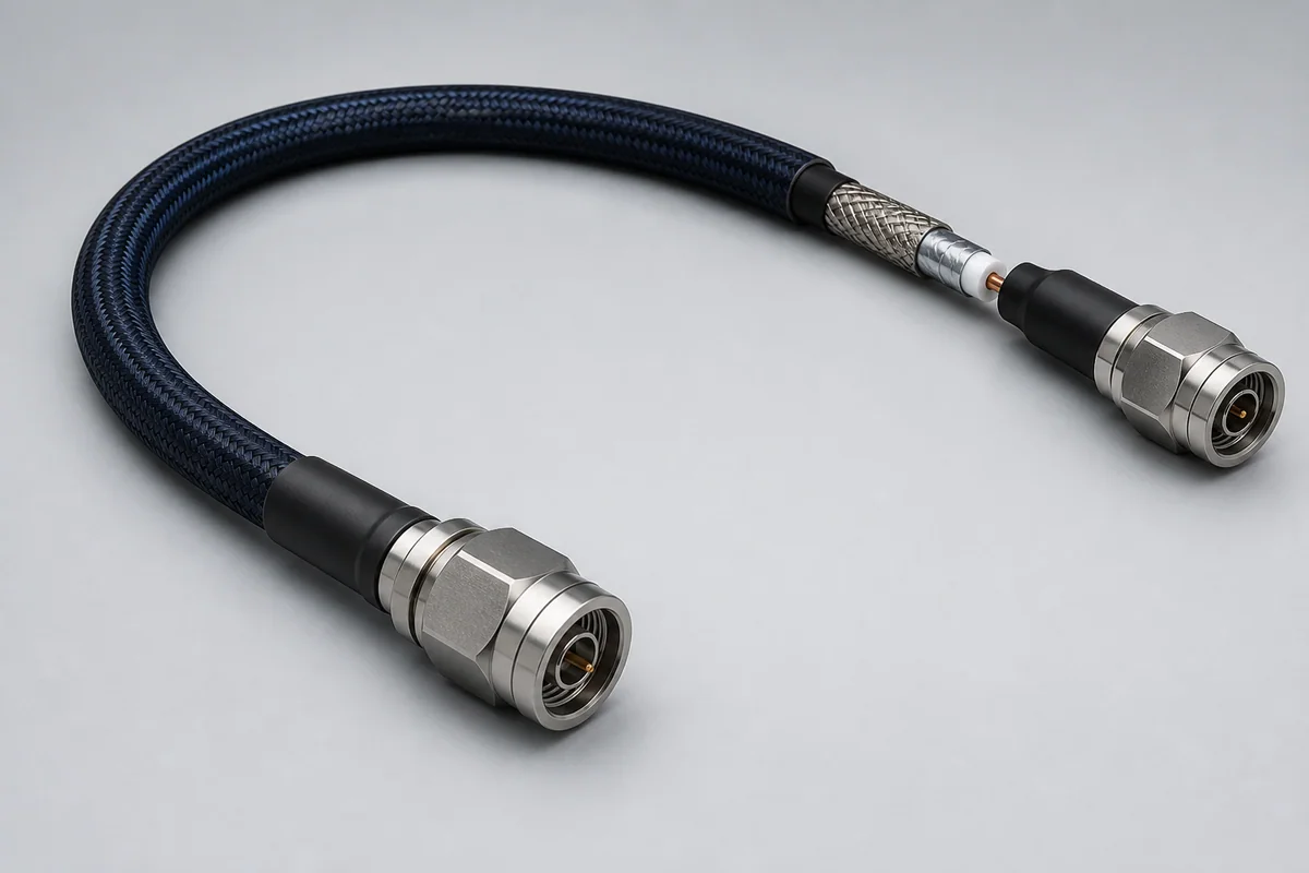
General-Purpose Microwave RF Assemblies
CM-RF-GENERAL

General-Purpose Microwave RF Assemblies

Reference configuration: Flexible low-loss RF interconnect direction for internal equipment, module-to-module, bench and environmental-test links, balancing compact routing, shielding and long-term amplitude/phase stability.

Reference · Flexible low-loss directionReference · Amplitude/phase stability
View specifications
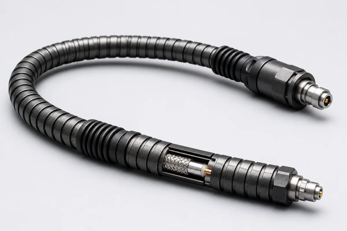
Ruggedized RF Test Assemblies
CM-RF-RUGGED-TEST

Ruggedized RF Test Assemblies

Reference configuration: Cable, connector and strain-relief systems reinforced for frequent flexing, mating, twisting and accidental mechanical loads in laboratories, production lines and field testing.

Reference · Crush and kink resistance directionReference · Repeatable measurement
View specifications
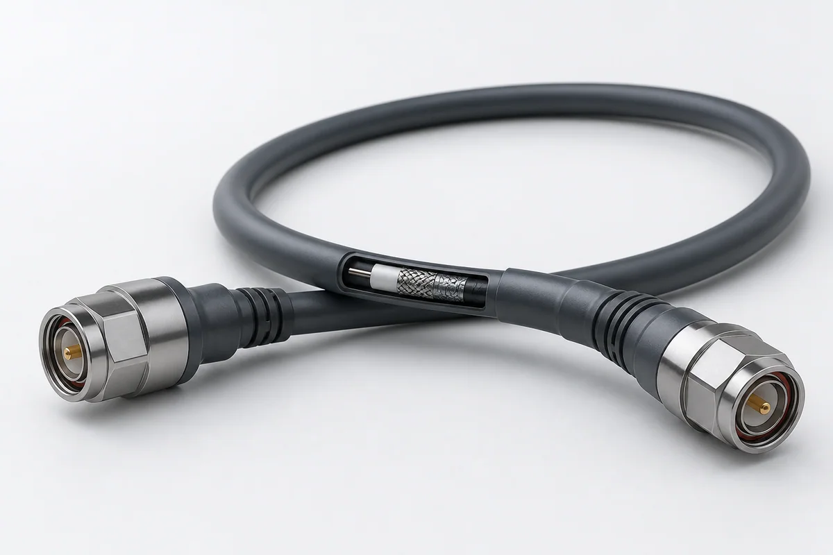
VNA RF Test Assemblies
CM-RF-VNA

VNA RF Test Assemblies

Reference configuration: Precision vector-network-analyzer paths using low-springback flexible construction, precision connectors and controlled assembly to improve reconnect repeatability and measurement stability between calibrations.

Reference · Precision repeatabilityReference · Low-springback flexibility
View specifications