conmoly 鑫聚新材
中文Request a Quote

CONMOLY / ENGINEERING & CONNECTIVITY

Tethered Drone Hybrid Cables

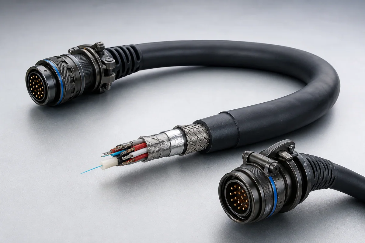
Reference configuration: High-voltage power, data pairs and single-mode fiber are integrated into a low-mass, weatherproof, crush-resistant tether for continuous drone power and secure high-bandwidth communication.

Tethered drone power data fiber hybrid cable construction
Product form illustration · Final construction depends on configuration

Specialty Products (Aerospace & Defense)

CM-SPECIAL-TETHER

Tethered Drone Cables

Reference configurations only; specifications and certifications require confirmation.

  • Reference · 250/600 Vrms
  • Reference · Single-mode fiber
  • Reference · 20% smaller than nylon cable

Reference specifications

Selection reference. Published third-party figures below describe specific reference configurations; they are not Conmoly guaranteed values or certifications. Confirm the final construction and test requirements with engineering.

Power pair, data pair and fiber are separate functional units; optical attenuation may increase above 85 °C.

Scroll the table horizontally to view all configuration conditions.

ParameterReference valueConfiguration / condition
Operating voltage250 / 600 VrmsPower pair / data pair
Test voltage1500 VrmsPower and data pairs
Maximum optical loss0.35 dB/km @ 1310 nmSingle-mode fiber
Maximum optical loss0.20 dB/km @ 1550 nmSingle-mode fiber
Insulation wall0.14 mmPower and data pairs
Diameter reduction20% smallerVersus nylon tether cables
Power gauges16 · 20 · 24 AWGStandard part-number direction

Reference source: www.gore.com

Available configurations

Power + fiberContinuous power with EMI-immune optical communication.
Power + data + fiberControl, high-speed data and video return in one tether.
Multiple power gauges16/20/24 AWG power pairs selected by altitude and load.

Cable construction

Functional unitsPower, data, fiber, video and discrete units are separated by function.
Unit isolationTwists, coax, individual shields and spacing manage coupling.
Strength or overall shieldTensile load, return path and platform grounding determine the structure.
Sealed rugged coverResists fluids, abrasion, temperature, repeated deployment and mission loads.
Mission terminationConnectors, branches, marking, strain relief and rapid-service interfaces are integrated.

Selection checklist

Interface documentPinout, protocols, connector and standard revision
Power and signalVoltage, current, bandwidth, optical path and shield zoning
Mechanical boundaryLength, diameter, mass, tensile load and bend radius
Mission environmentTemperature, fluids, abrasion, vibration, shock and sealing
OperationReel, release, mating, maintenance and storage cycles
Acceptance matrixElectrical, mechanical, environmental and system tests

Applications

  • EO/IR sensor platforms
  • HD camera and video return
  • ISR and search/rescue
  • Temporary communications and aerial cell sites

Interfaces & termination

  • Hybrid power, data and fiber construction
  • Mission connector, branch and strain relief
  • Fixed-length complete and serialized assembly

Project validation checklist

  • Pin-by-pin continuity, insulation, hipot and wire map
  • High-speed, fiber or RF unit performance
  • Tensile, flex, abrasion, sealing and termination retention
  • Interface-standard environment and system integration

Standard and product names identify the target interface only and do not imply unverified compliance, qualification or platform approval.

MIL-STD-1760 Umbilical Assemblies
CM-SPECIAL-1760

MIL-STD-1760 Umbilical Assemblies

Reference configuration: Sealed high-flex hybrid umbilicals for aircraft pylon and mission-store interfaces use controlled disconnect load, EMI shielding and long flex life for safe release and repeat maintenance.

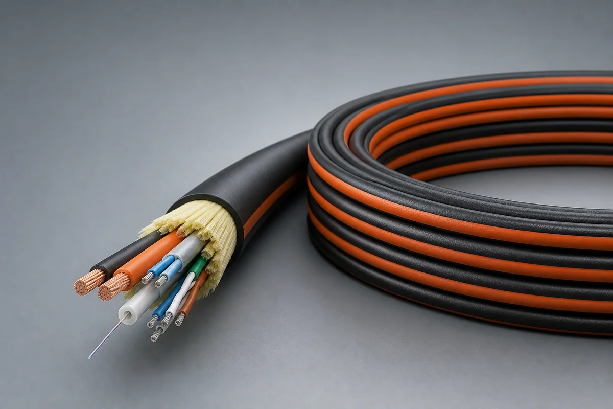
Reference · >100,000 flex cyclesReference · 100 releases
View specifications