CAN / CAN FD · 120 Ω
Single shielded twisted-pair trunk
Wide-temperature standard construction
Avionics, vehicle and industrial control trunks
Enquire about this configuration
CONMOLY / ENGINEERING & CONNECTIVITY
Reference configuration: 120-ohm controlled shielded twisted-pair links for aerospace, vehicle and industrial control networks, defined around CAN / CAN FD topology, common-mode noise, termination, node count and rugged routing.
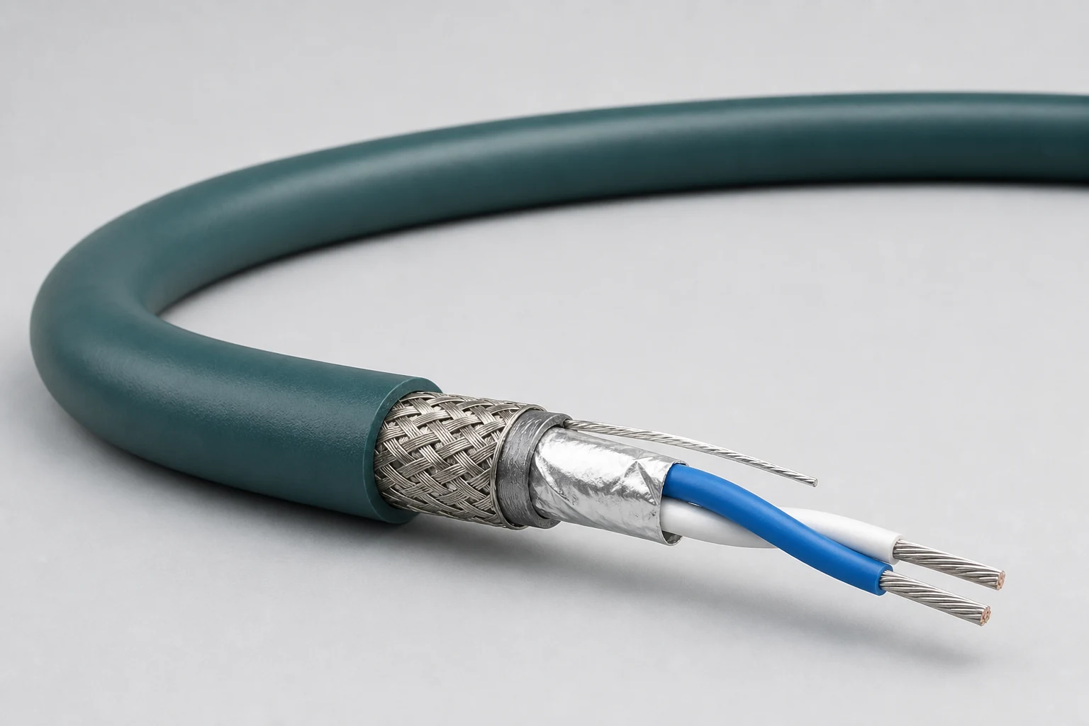
Data Cables
CM-DATA-CAN
CAN Bus Cables
Reference configurations only; specifications and certifications require confirmation.
Selection reference. Published third-party figures below describe specific reference configurations; they are not Conmoly guaranteed values or certifications. Confirm the final construction and test requirements with engineering.
Dielectric withstand and weight vary between standard and ultralight versions; the applicable construction is identified for each value.
Scroll the table horizontally to view all configuration conditions.
| Parameter | Reference value | Configuration / condition |
|---|---|---|
| Maximum frequency | 1 GHz | CAN bus construction |
| Characteristic impedance | 120 ± 10 Ω | Nominal value |
| Typical operating voltage | < 48 V | System operating condition |
| Velocity / delay | 80% · 4.10 ns/m | Typical transmission values |
| Capacitance | 42.0 pF/m | Typical value |
| Dielectric withstand | 1500 / 700 Vrms | Conductor-conductor; version dependent |
| Operating temperature | −65 to +200 °C | Standard versions |
| Diameter / MBR / weight | 4.2 mm · 21.0 mm · 17.5 g/m | Ultralight 24 AWG, DXN2657-24 |
Reference source: www.gore.com
| Single bus pair | A compact shielded or unshielded pair for a primary CAN channel. |
|---|---|
| Redundant bus | Two controlled pairs combined for dual-channel or fault-tolerant system architecture. |
| Hybrid CAN construction | CAN pairs combined with power, discretes or other signals in one cable while managing coupling. |
Solution codes support topology and construction discussions; they do not replace complete network design. Final part number must account for node count, trunk and stub length, termination and connectors.
Single shielded twisted-pair trunk
Wide-temperature standard construction
Avionics, vehicle and industrial control trunks
Enquire about this configuration24 AWG ultralight shielded pair
4.2 mm · 21.0 mm MBR · 17.5 g/m
Mass- and routing-sensitive platforms
Enquire about this configurationTwo independently shielded bus units
Project-defined isolation, grounding and termination
Redundant control, mission systems and common harnesses
Enquire about this configurationZoned bus unit and power conductors
Confirm crosstalk, voltage drop and thermal rise
Distributed sensors, actuators and remote nodes
Enquire about this configuration| Balanced conductors | Resistance and size support network length, voltage margin and termination. |
|---|---|
| Pair insulation | Defines pair spacing and dielectric behavior. |
| Controlled twist | Supports impedance balance and common-mode rejection. |
| Optional shield | Configured from EMC zone, grounding and connector design. |
| Rugged jacket | Matches vehicle, aerospace or industrial installation loads. |
| Network variant | CAN, CAN FD or project-specific physical layer |
|---|---|
| Topology | Bus length, stubs, node count and termination scheme |
| Bit rate | Target rate and timing margin |
| Shield/ground | Unshielded, shielded, drain and shell termination |
| Mechanical | Diameter, bend, flex, vibration and abrasion |
| Environment | Temperature, fluids, flame and platform requirements |
Bus length, stub length, bit rate and EMC capability are system properties and must be validated with the actual nodes and termination network.
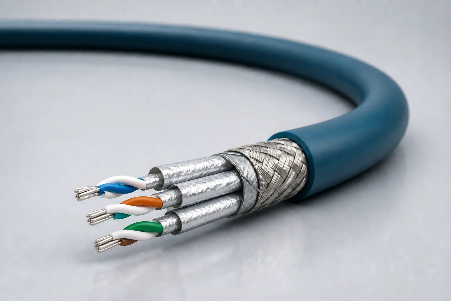
Reference configuration: Controlled-impedance interconnects for avionics, mission equipment, high-speed vision and precision industrial networks, spanning Cat 5e, Cat 6A and Cat 8 directions with insertion loss, return loss, crosstalk and skew managed as a complete channel.
View specifications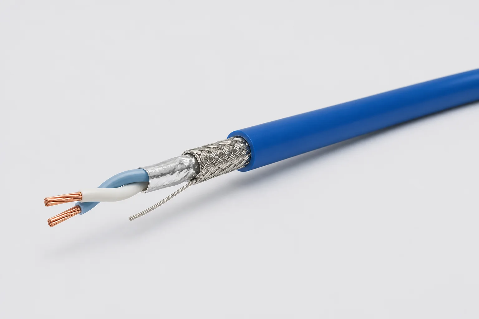
Reference configuration: 100-ohm single-pair shielded cable for aerospace, vehicle and precision-equipment differential links through 1 GHz, using controlled twist, foil, braid and drain paths to manage impedance, common-mode noise and wide-temperature reliability.
View specifications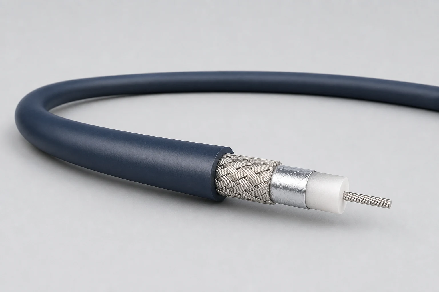
Reference configuration: Precision concentric transmission paths for video, timing, instrumentation and sensitive single-ended signals, spanning 50- and 75-ohm directions with frequency, loss, shielding and connector transitions defined as a complete assembly.
View specifications