Ethernet / USB · up to 1 GHz
Parallel differential units, zoned shielding and low-particle surface
> 10 million cycles · 50 mm dynamic bend radius
High-speed stages, metrology and data acquisition
Enquire about this configuration
CONMOLY / ENGINEERING & CONNECTIVITY
Reference configuration: High-speed flat data cable for semiconductor and precision-motion equipment, supporting directions through 1 GHz and Ethernet, FireWire, USB and CoaXPress with more than 10 million flex cycles at a 50 mm dynamic bend radius and an ISO Class 1 cleanroom direction.
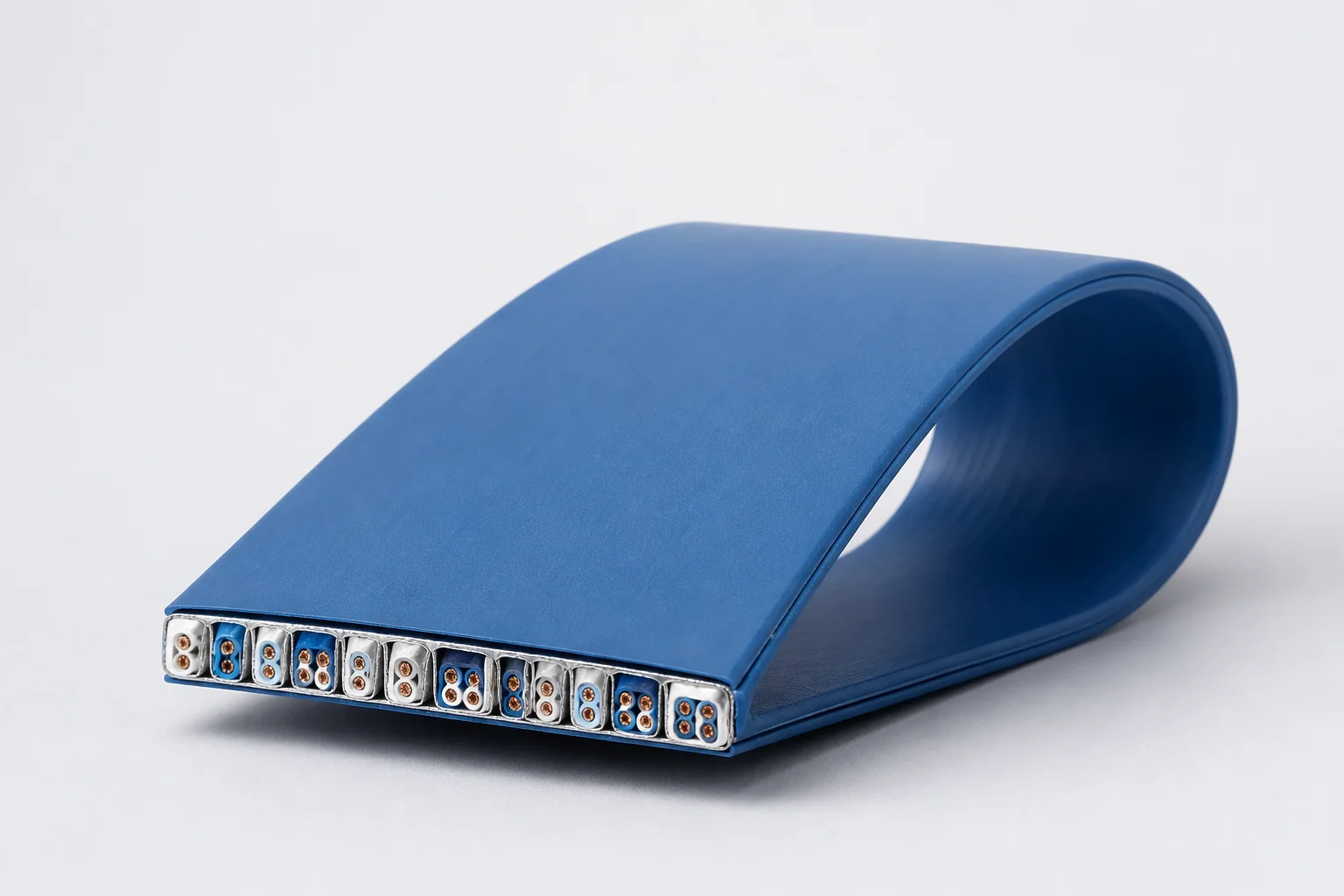
Data Cables
CM-DATA-FLAT
Flat Cables
Reference configurations only; specifications and certifications require confirmation.
Selection reference. Published third-party figures below describe specific reference configurations; they are not Conmoly guaranteed values or certifications. Confirm the final construction and test requirements with engineering.
Flex life and cleanliness are affected by stroke, bend radius and acceleration and should be validated against the application.
Scroll the table horizontally to view all configuration conditions.
| Parameter | Reference value | Configuration / condition |
|---|---|---|
| Maximum frequency | 1 GHz | High-speed flat data cable |
| Dynamic flex life | > 10 million cycles | Standard test condition |
| Minimum dynamic bend radius | 50 mm | Dynamic bend condition |
| Cleanroom rating | ISO Class 1 | Cleanroom application configuration |
| Supported protocols | Ethernet · FireWire · USB · CoaXPress | Cable-construction dependent |
Reference source: www.gore.com
| High-speed differential flat cable | Positions Ethernet or USB differential units to manage impedance, crosstalk and dynamic skew. |
|---|---|
| Machine-vision flat cable | Integrates CoaXPress or other camera-signal units while preserving geometry through repeated travel. |
| Data-and-power hybrid flat cable | Combines FireWire, control or low-voltage power units to reduce cable count on moving stages. |
Solution codes support early protocol, motion and cleanliness matching. Final part number, flat dimensions, channel layout, termination and life conditions are confirmed against equipment stroke and test specification.
Parallel differential units, zoned shielding and low-particle surface
> 10 million cycles · 50 mm dynamic bend radius
High-speed stages, metrology and data acquisition
Enquire about this configurationVideo-signal units with flat reinforcement and slip layers
ISO Class 1 cleanroom direction
Machine vision, wafer inspection and high-speed imaging
Enquire about this configurationZoned data, control and power units
Validate crosstalk, voltage drop and flex life together
Wafer handling, motion control and multifunction stages
Enquire about this configuration| Signal conductors | Parallel positions are defined from channel count, current and signal integrity. |
|---|---|
| Low-loss insulation | Controls impedance while supporting a thin flexible profile. |
| Shield architecture | Pair, zone or overall shields manage crosstalk and external noise. |
| Flat reinforcement | Controls neutral axis, conductor migration and planar flex. |
| Clean outer surface | Supports equipment routing and selected cleanliness requirements. |
| Signal set | Channel count, protocol, impedance and data rate |
|---|---|
| Geometry | Pitch, width, thickness and bend direction |
| Motion | Stroke, radius, speed, acceleration and cycle target |
| Clean environment | Cleanroom class direction, particles, ESD and vacuum |
| Termination | Connector pitch, contact map and strain relief |
| Installation | Guide surfaces, free length, clamps and service access |
Cleanroom class, flex life and protocol performance depend on materials, stroke, bend radius, speed and acceleration and require validation on the installed motion profile.
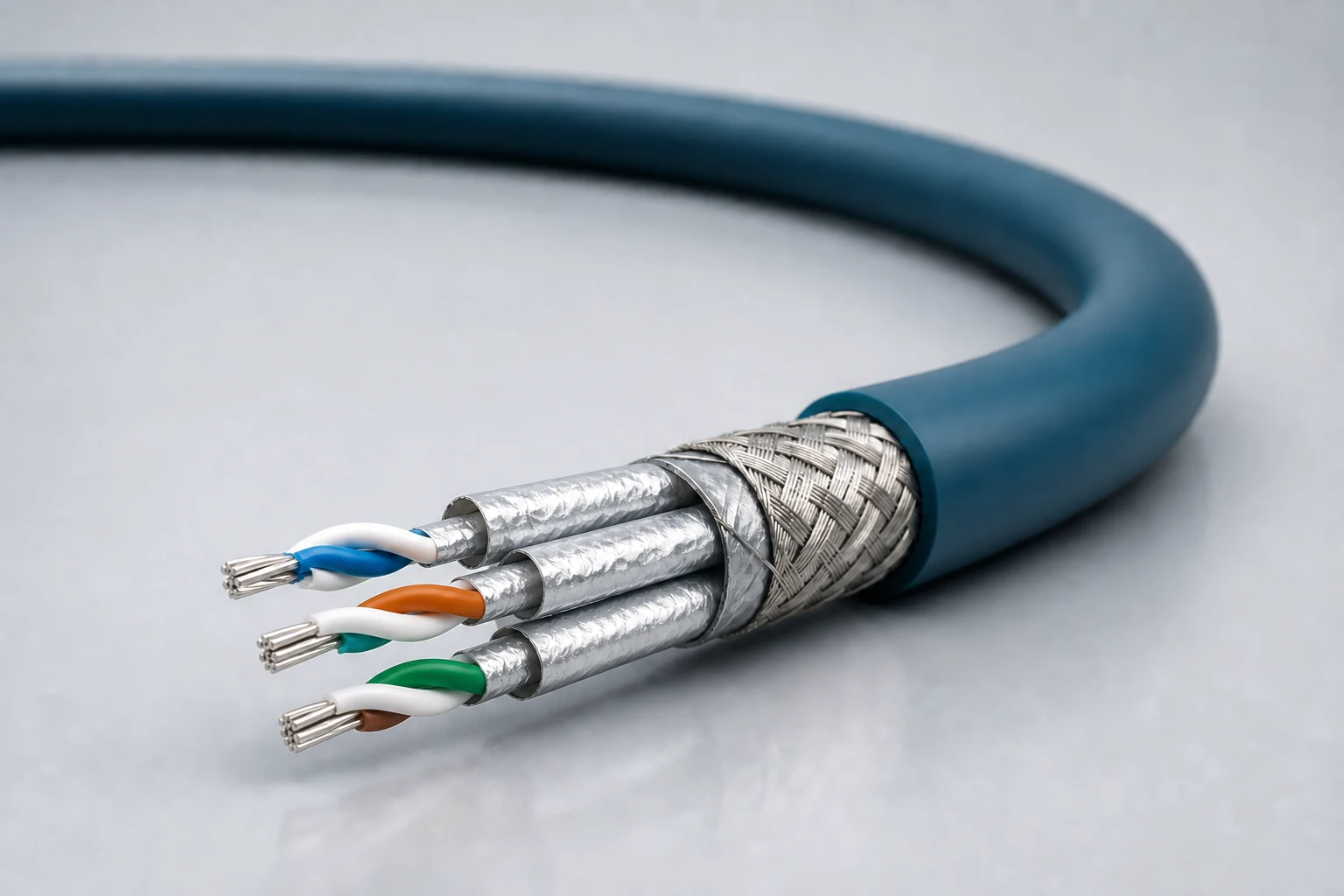
Reference configuration: Controlled-impedance interconnects for avionics, mission equipment, high-speed vision and precision industrial networks, spanning Cat 5e, Cat 6A and Cat 8 directions with insertion loss, return loss, crosstalk and skew managed as a complete channel.
View specifications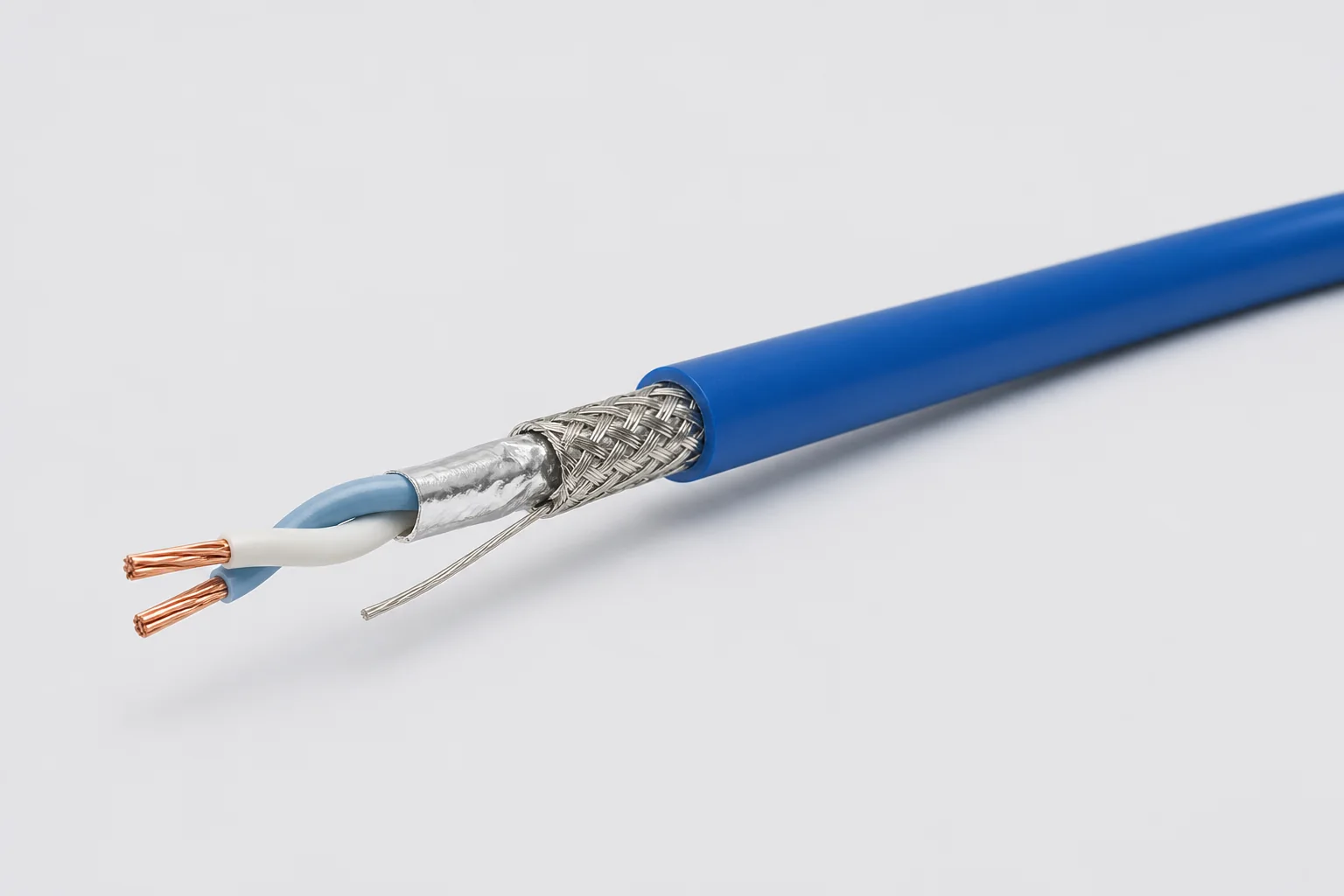
Reference configuration: 100-ohm single-pair shielded cable for aerospace, vehicle and precision-equipment differential links through 1 GHz, using controlled twist, foil, braid and drain paths to manage impedance, common-mode noise and wide-temperature reliability.
View specifications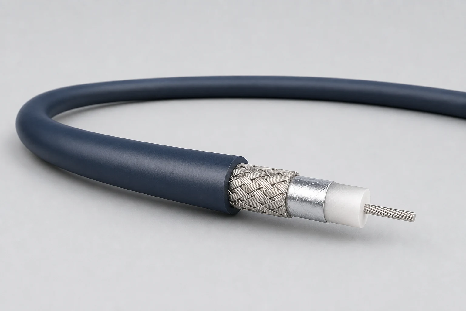
Reference configuration: Precision concentric transmission paths for video, timing, instrumentation and sensitive single-ended signals, spanning 50- and 75-ohm directions with frequency, loss, shielding and connector transitions defined as a complete assembly.
View specifications