75 Ω / up to 12 GHz
Concentric dielectric plus composite outer conductor
< 420 V · 85% velocity
Digital video, cameras, displays and precision measurement
Enquire about this configuration
CONMOLY / ENGINEERING & CONNECTIVITY
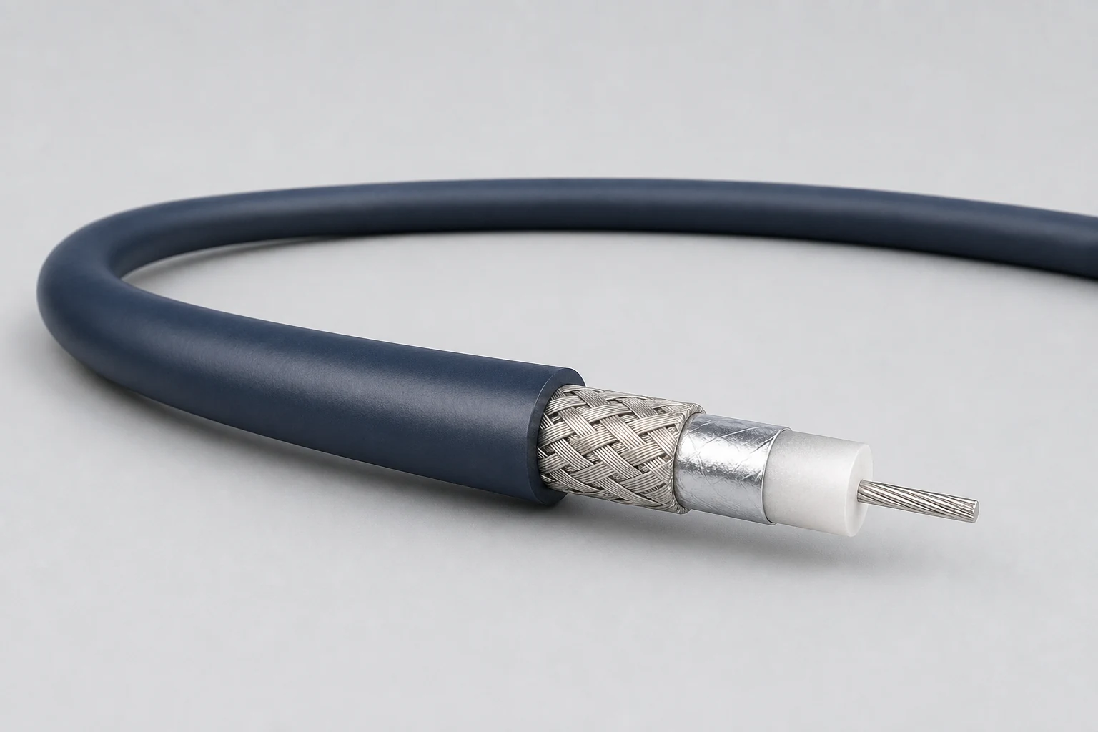
Reference configuration: Precision concentric transmission paths for video, timing, instrumentation and sensitive single-ended signals, spanning 50- and 75-ohm directions with frequency, loss, shielding and connector transitions defined as a complete assembly.
Data Cables
CM-DATA-COAX
Coaxial Cables
Reference configurations only; specifications and certifications require confirmation.
Selection reference. Published third-party figures below describe specific reference configurations; they are not Conmoly guaranteed values or certifications. Confirm the final construction and test requirements with engineering.
The 50 Ω and 75 Ω constructions are separate configurations; values are listed against the applicable impedance version.
Scroll the table horizontally to view all configuration conditions.
| Parameter | Reference value | Configuration / condition |
|---|---|---|
| Maximum frequency | 12 GHz | 75 Ω version |
| Characteristic impedance | 75 ± 2 Ω | 75 Ω version |
| Operating voltage / velocity | < 420 V · 85% | 75 Ω version |
| Capacitance / shielding | 53.2 pF/m · > 70 dB | 75 Ω; shielding through 2 MHz |
| Maximum frequency | 3 GHz | 50 Ω version |
| Characteristic impedance | 50 ± 2 Ω | 50 Ω version |
| Voltage / velocity / capacitance | 250 V · > 80% · 80 pF/m | 50 Ω version |
| Operating temperature | −65 to +200 °C | 50 Ω and 75 Ω versions |
Reference source: www.gore.com
| 75-ohm high-bandwidth video coax | For digital video, cameras, displays and precision measurement links through 12 GHz. |
|---|---|
| 50-ohm instrumentation coax | For timing, sensing, instrumentation and equipment-module links through 3 GHz. |
| Micro-coax construction | Reduces diameter and mass inside equipment, multi-coax connectors and dense assemblies. |
Solution codes support early impedance, frequency and installation matching. Final part number, attenuation curve, dimensions and connector transition are frozen after assembly specification approval.
Concentric dielectric plus composite outer conductor
< 420 V · 85% velocity
Digital video, cameras, displays and precision measurement
Enquire about this configurationFlexible 50-ohm coaxial core
250 V · > 80% velocity
Timing, sensors, instrumentation and module interconnect
Enquire about this configurationMicro single- or multi-coax bundle
Confirm cross-section, loss and bend together
Dense cameras, internal equipment and connector assemblies
Enquire about this configuration| Center conductor | Solid or stranded geometry selected for attenuation, flexibility and termination. |
|---|---|
| Dielectric | Concentric low-loss insulation establishes impedance and electrical length. |
| Outer conductor | Foil, braid or composite return path provides shielding and mechanical stability. |
| Jacket | Protects the coax while controlling diameter, friction and bend behavior. |
| Connector transition | Termination geometry is treated as part of the impedance-controlled path. |
| Impedance | 50 Ω, 75 Ω or project-defined target |
|---|---|
| Frequency/data content | Highest frequency, edge rate and link budget |
| Length | Assembly length, tolerance and connector transitions |
| Size and flex | Outer diameter, bend radius and motion |
| Shielding | Coverage, leakage target and grounding |
| Interface | Cable-end connector, board transition or bundled harness |
Impedance and loss values are established for a defined cable size, length, frequency range and connector configuration.
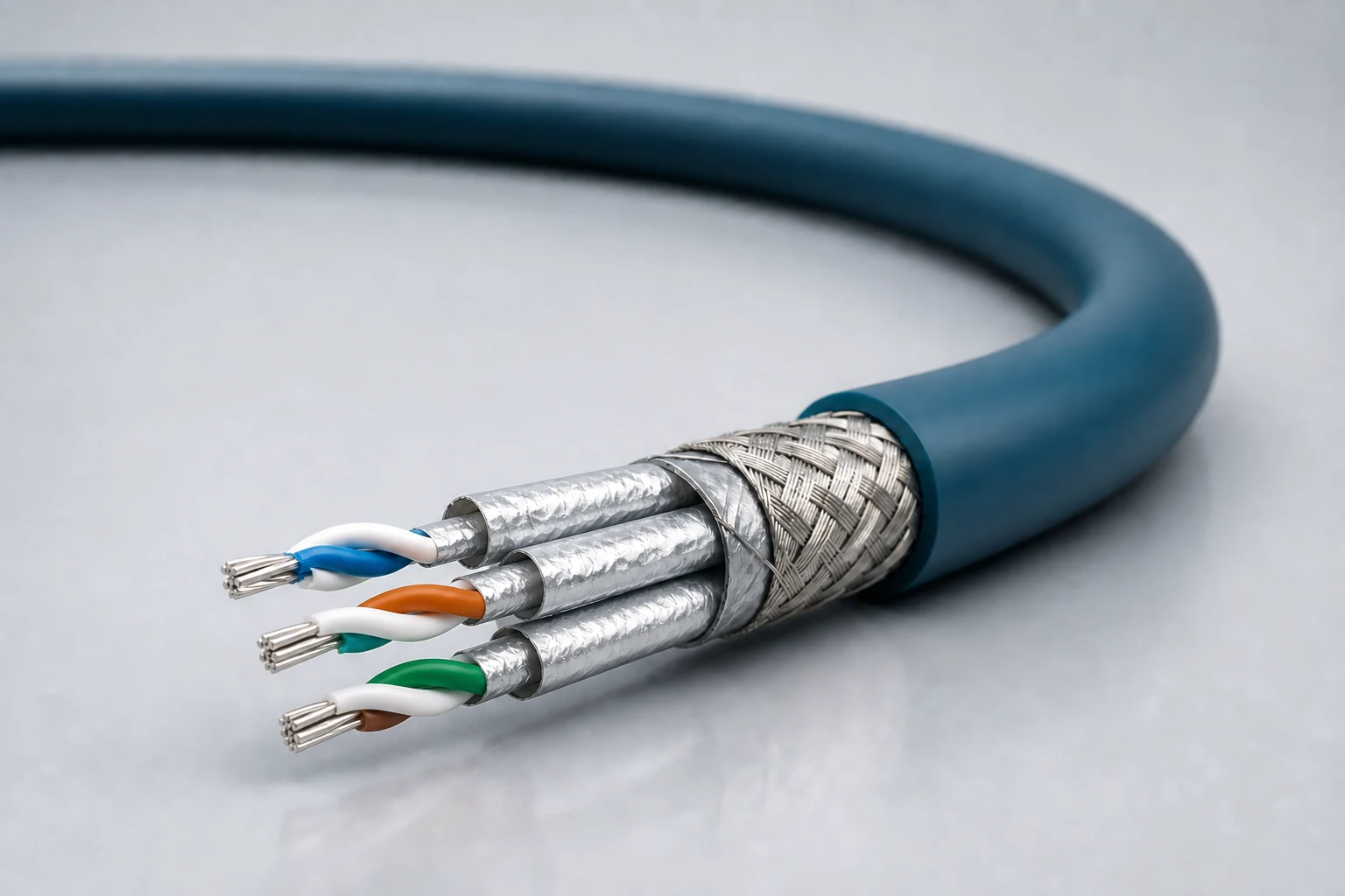
Reference configuration: Controlled-impedance interconnects for avionics, mission equipment, high-speed vision and precision industrial networks, spanning Cat 5e, Cat 6A and Cat 8 directions with insertion loss, return loss, crosstalk and skew managed as a complete channel.
View specifications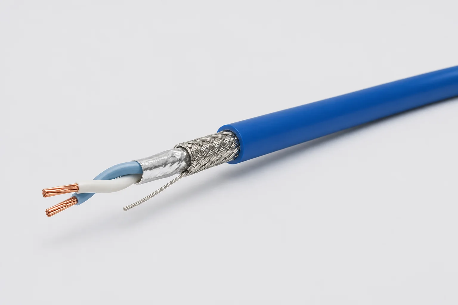
Reference configuration: 100-ohm single-pair shielded cable for aerospace, vehicle and precision-equipment differential links through 1 GHz, using controlled twist, foil, braid and drain paths to manage impedance, common-mode noise and wide-temperature reliability.
View specifications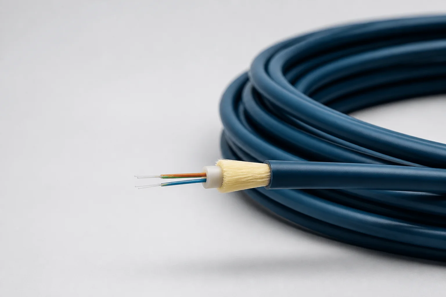
Reference configuration: Lightweight fiber-optic cable for aerospace and defense high-bandwidth interconnects, spanning singlemode and OM1–OM5 multimode directions through 100 Gb/s with PFA, FEP or PEEK jackets and buffered strength systems controlling optical loss, microbend and wide-temperature protection.
View specifications