Multimode · up to 100 Gb/s
1.8 mm simplex with buffer, aramid strength and rugged jacket
≤ 5.0 dB/km @ 850 nm · ≤ 3.0 dB/km @ 1300 nm
Avionics backbones, HD video and high-reliability box links
Enquire about this configuration
CONMOLY / ENGINEERING & CONNECTIVITY
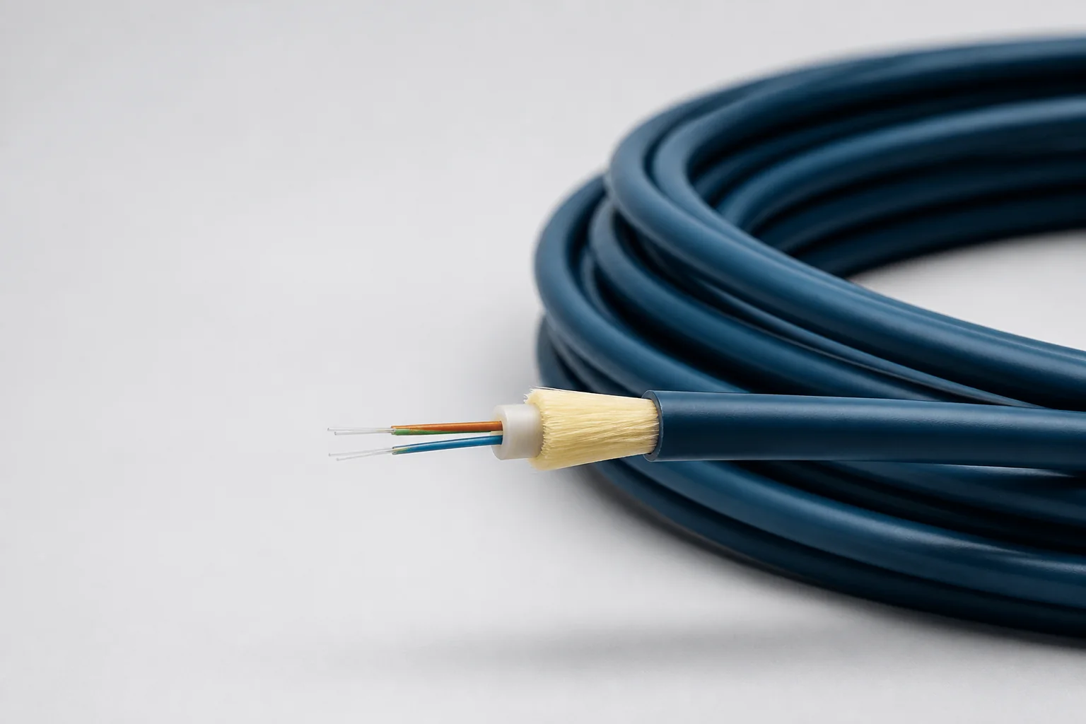
Reference configuration: Lightweight fiber-optic cable for aerospace and defense high-bandwidth interconnects, spanning singlemode and OM1–OM5 multimode directions through 100 Gb/s with PFA, FEP or PEEK jackets and buffered strength systems controlling optical loss, microbend and wide-temperature protection.
Data Cables
CM-DATA-FIBER
Fiber Optic Cables
Reference configurations only; specifications and certifications require confirmation.
Selection reference. Published third-party figures below describe specific reference configurations; they are not Conmoly guaranteed values or certifications. Confirm the final construction and test requirements with engineering.
Optical loss, temperature and jacket material vary by diameter, fiber class and part number; the final specification must identify the exact part number.
Scroll the table horizontally to view all configuration conditions.
| Parameter | Reference value | Configuration / condition |
|---|---|---|
| Maximum data rate | 100 Gb/s | 1.8 / 1.2 / 0.9 mm simplex constructions |
| Maximum optical loss | ≤ 5.0 dB/km @ 850 nm | 1.8 mm multimode configuration limit |
| Maximum optical loss | ≤ 3.0 dB/km @ 1300 nm | 1.8 mm multimode configuration |
| Maximum optical loss | ≤ 1.5 dB/km @ 1300 nm | 1.2 mm configuration |
| Optical loss | 3.0 / 1.0 dB/km | 0.9 mm; 850 / 1310 nm |
| Operating temperature | −65 to +135 °C | 1.8 mm and 0.9 mm versions |
| Jacket / fiber classes | PFA · FEP · PEEK / SM · OM1–OM5 | Configuration dependent |
Reference source: www.gore.com
| 1.8 mm rugged simplex | A protected multimode high-bandwidth channel with fuller buffer, strength and jacket layers. |
|---|---|
| 1.2 mm lightweight simplex | Balances mechanical protection with small-diameter routing for box-to-box and internal links. |
| 0.9 mm compact optical unit | For dense connectors, breakout assemblies and space-constrained internal equipment. |
Solution codes support early fiber-class, diameter and environment matching. Final part number, numerical aperture, wavelength, jacket, connectors and complete optical budget are confirmed to the system configuration.
1.8 mm simplex with buffer, aramid strength and rugged jacket
≤ 5.0 dB/km @ 850 nm · ≤ 3.0 dB/km @ 1300 nm
Avionics backbones, HD video and high-reliability box links
Enquire about this configuration1.2 mm lightweight simplex construction
≤ 1.5 dB/km @ 1300 nm
Lightweight box links and dense airborne harnesses
Enquire about this configuration0.9 mm optical unit with PFA/FEP/PEEK direction
3.0 / 1.0 dB/km @ 850 / 1310 nm
Connector breakouts, internal equipment and confined links
Enquire about this configuration| Optical fiber | Singlemode or multimode glass selected for the optical system. |
|---|---|
| Primary coating/buffer | Protects the glass and manages microbend sensitivity. |
| Strength member | Carries tensile load and separates installation stress from the fiber. |
| Protective jacket | Configured for abrasion, flex, cleanliness, flame or vacuum direction. |
| Optical termination | Ferrule, polish, alignment and strain relief are controlled as a process. |
| Optical system | Wavelength, source, receiver and allowable optical budget |
|---|---|
| Fiber type | Singlemode, multimode, simplex, duplex or multifiber |
| Length and routing | Installed length, bend radius and pull path |
| Mechanical load | Tension, crush, flex, vibration and connector retention |
| Environment | Temperature, cleanliness, vacuum, fluids or flame |
| Termination | Connector family, polish, breakout and inspection method |
Optical performance depends on fiber class, wavelength, diameter, connector finish, length, bend state and contamination control; the complete link must be verified.
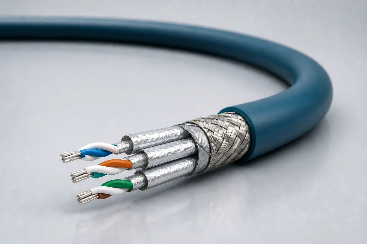
Reference configuration: Controlled-impedance interconnects for avionics, mission equipment, high-speed vision and precision industrial networks, spanning Cat 5e, Cat 6A and Cat 8 directions with insertion loss, return loss, crosstalk and skew managed as a complete channel.
View specifications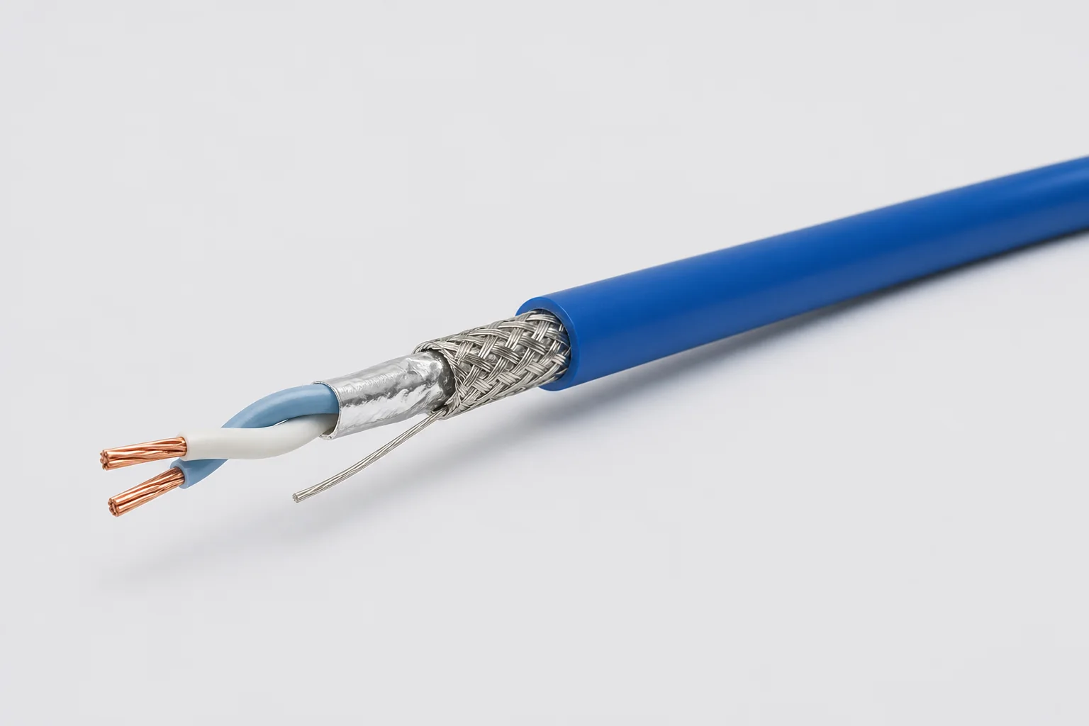
Reference configuration: 100-ohm single-pair shielded cable for aerospace, vehicle and precision-equipment differential links through 1 GHz, using controlled twist, foil, braid and drain paths to manage impedance, common-mode noise and wide-temperature reliability.
View specifications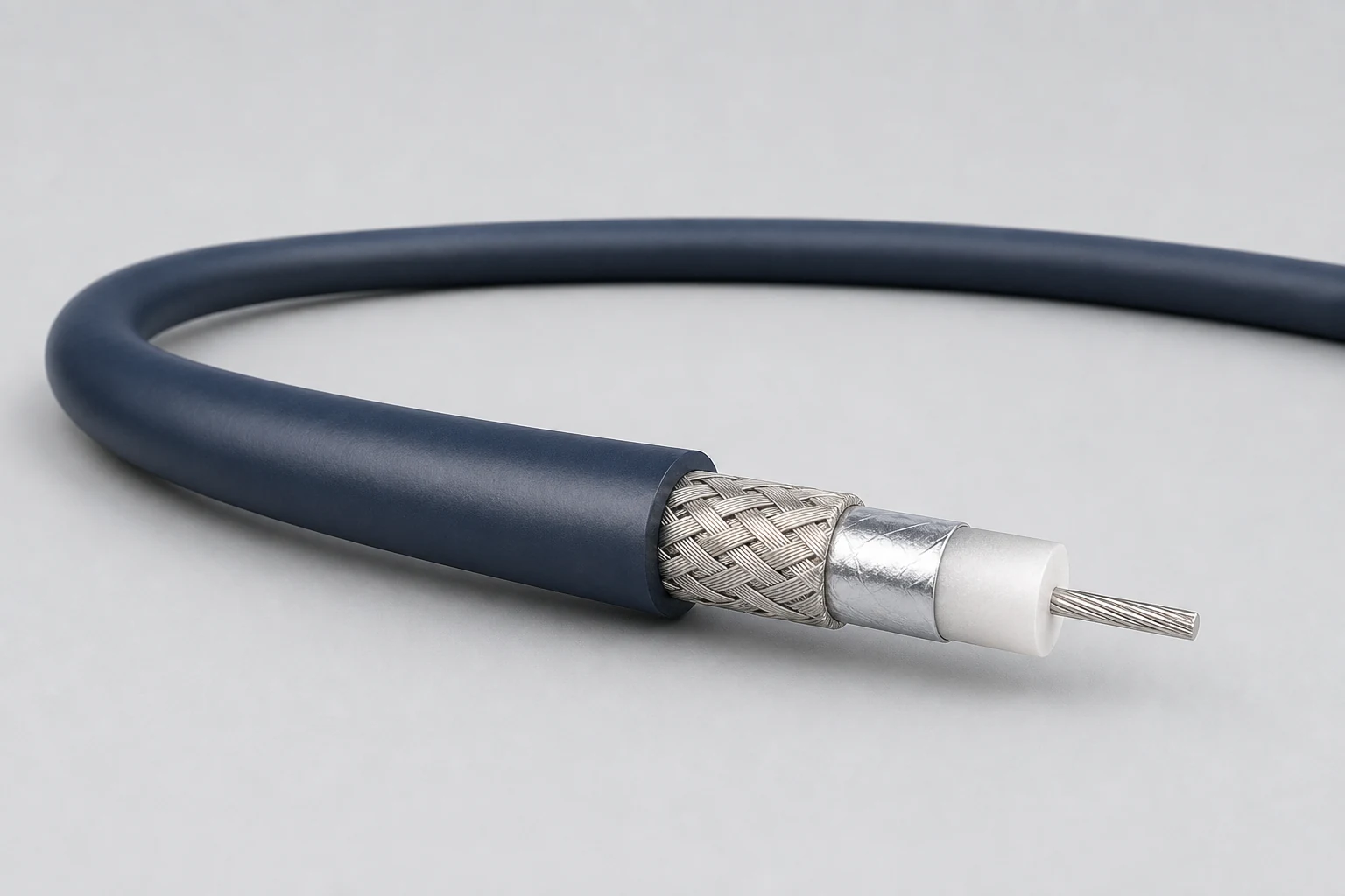
Reference configuration: Precision concentric transmission paths for video, timing, instrumentation and sensitive single-ended signals, spanning 50- and 75-ohm directions with frequency, loss, shielding and connector transitions defined as a complete assembly.
View specifications