Differential data · up to 1 GHz
24 AWG single pair with foil/braid composite shield
3.30 mm · 16.2 mm MBR · 12.8 g/m
Avionics, sensors and mass-sensitive equipment
Enquire about this configuration
CONMOLY / ENGINEERING & CONNECTIVITY
Reference configuration: 100-ohm single-pair shielded cable for aerospace, vehicle and precision-equipment differential links through 1 GHz, using controlled twist, foil, braid and drain paths to manage impedance, common-mode noise and wide-temperature reliability.
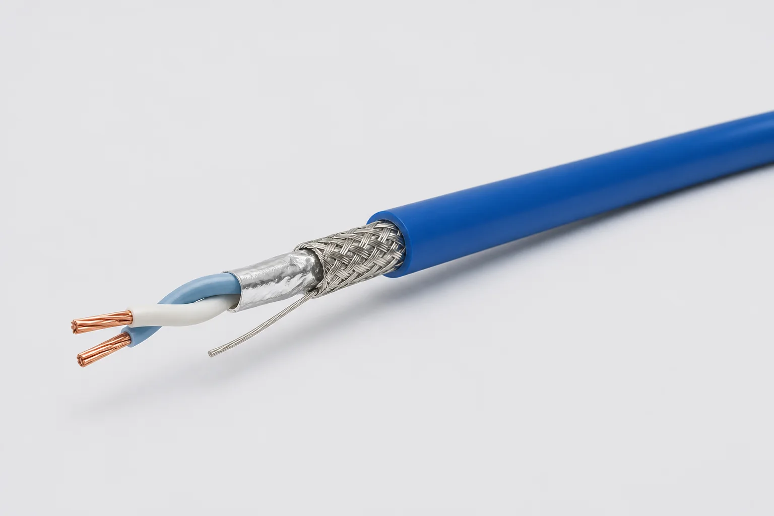
Data Cables
CM-DATA-STP
Shielded Twisted Pair Cables
Reference configurations only; specifications and certifications require confirmation.
Selection reference. Published third-party figures below describe specific reference configurations; they are not Conmoly guaranteed values or certifications. Confirm the final construction and test requirements with engineering.
Electrical and mechanical values apply to the fluoropolymer STP construction; polyurethane versions have a different temperature range.
Scroll the table horizontally to view all configuration conditions.
| Parameter | Reference value | Configuration / condition |
|---|---|---|
| Maximum frequency | 1 GHz | Shielded twisted-pair construction |
| Characteristic impedance | 100 ± 10 Ω | Nominal value |
| Typical operating voltage | < 48 V | System operating condition |
| Velocity / delay | 80% · 4.10 ns/m | Typical transmission values |
| Capacitance | 42.6 pF/m | Typical value |
| Dielectric withstand | 1500 / 1000 Vrms | Conductor-conductor / conductor-shield |
| Operating temperature | −65 to +200 °C | Fluoropolymer version |
| Diameter / MBR / weight | 3.30 mm · 16.2 mm · 12.8 g/m | Ultralight 24 AWG, DXN2656-24 |
Reference source: www.gore.com
| 24 AWG ultralight | A 3.30 mm diameter, 16.2 mm minimum bend radius and 12.8 g/m direction for smaller, lighter equipment harnesses. |
|---|---|
| Wide-temperature fluoropolymer | Maintains differential geometry, dielectric withstand and shield continuity from −65 to +200 °C. |
| Flexible polyurethane | For softer equipment routing; temperature, flame and fluid compatibility are confirmed by configuration. |
Solution codes support early impedance, gauge and environment matching. Final part number, jacket material, shield termination, connectors and complete-channel performance are confirmed in the technical specification.
24 AWG single pair with foil/braid composite shield
3.30 mm · 16.2 mm MBR · 12.8 g/m
Avionics, sensors and mass-sensitive equipment
Enquire about this configurationFluoropolymer insulation, drain and composite shield
−65 to +200 °C · < 48 V
Temperature-extreme platforms, mission equipment and vehicles
Enquire about this configurationPolyurethane jacket with shielded twisted-pair unit
Temperature and fluid compatibility by configuration
Internal equipment, service-intensive and flexible routing
Enquire about this configuration| Matched conductors | Conductor size and resistance balance are controlled for the receiving interface. |
|---|---|
| Primary insulation | Material and concentricity establish dielectric behavior and pair geometry. |
| Controlled twist | Lay length balances flexibility, common-mode behavior and pair stability. |
| Pair/overall shielding | Shield coverage, drain and grounding are selected from the EMI zone. |
| Protective jacket | Provides abrasion, environmental protection and termination support. |
| Signal interface | Target impedance, data rate, voltage and common-mode range |
|---|---|
| Pair count | Single pair, multi-pair or mixed-signal construction |
| Shield strategy | Individual, overall or combined shields and grounding |
| Routing | Round, low-profile, fixed, flexing or torsional |
| Environment | Temperature, vibration, fluids, flame and cleanliness |
| Termination | Connector contacts, backshell, drain and strip dimensions |
Frequency, impedance, shielding and protocol capability depend on the complete pair, connector and grounding implementation and require channel validation.
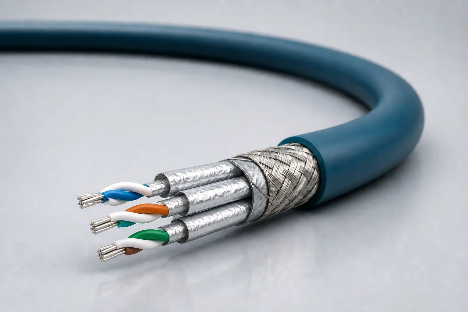
Reference configuration: Controlled-impedance interconnects for avionics, mission equipment, high-speed vision and precision industrial networks, spanning Cat 5e, Cat 6A and Cat 8 directions with insertion loss, return loss, crosstalk and skew managed as a complete channel.
View specifications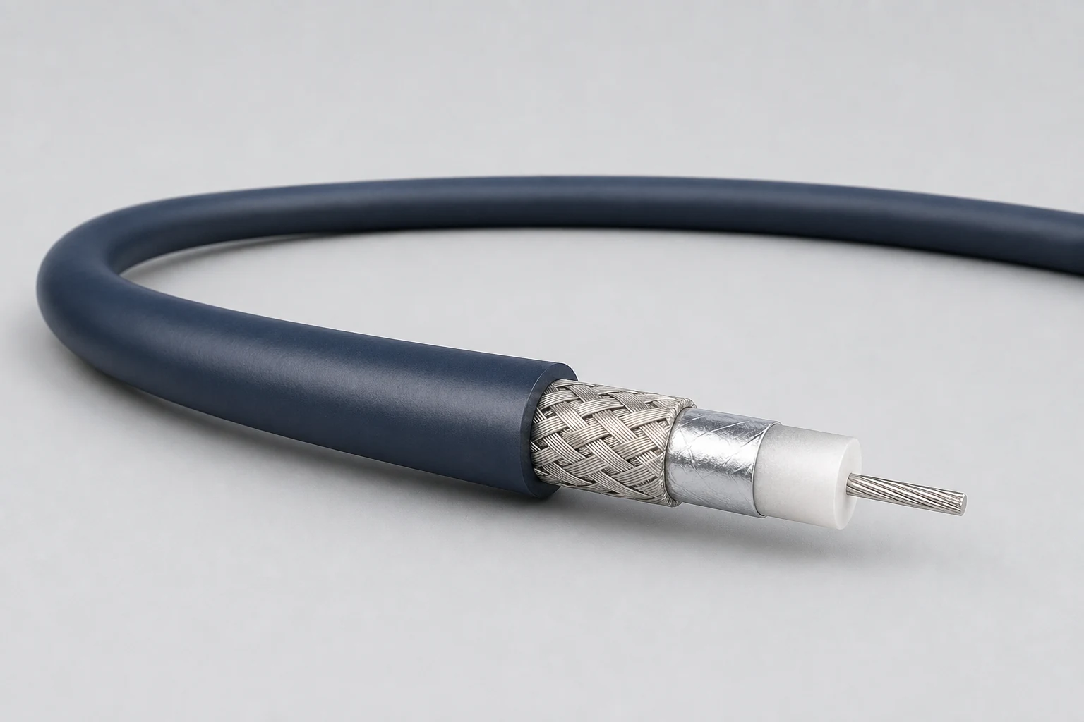
Reference configuration: Precision concentric transmission paths for video, timing, instrumentation and sensitive single-ended signals, spanning 50- and 75-ohm directions with frequency, loss, shielding and connector transitions defined as a complete assembly.
View specifications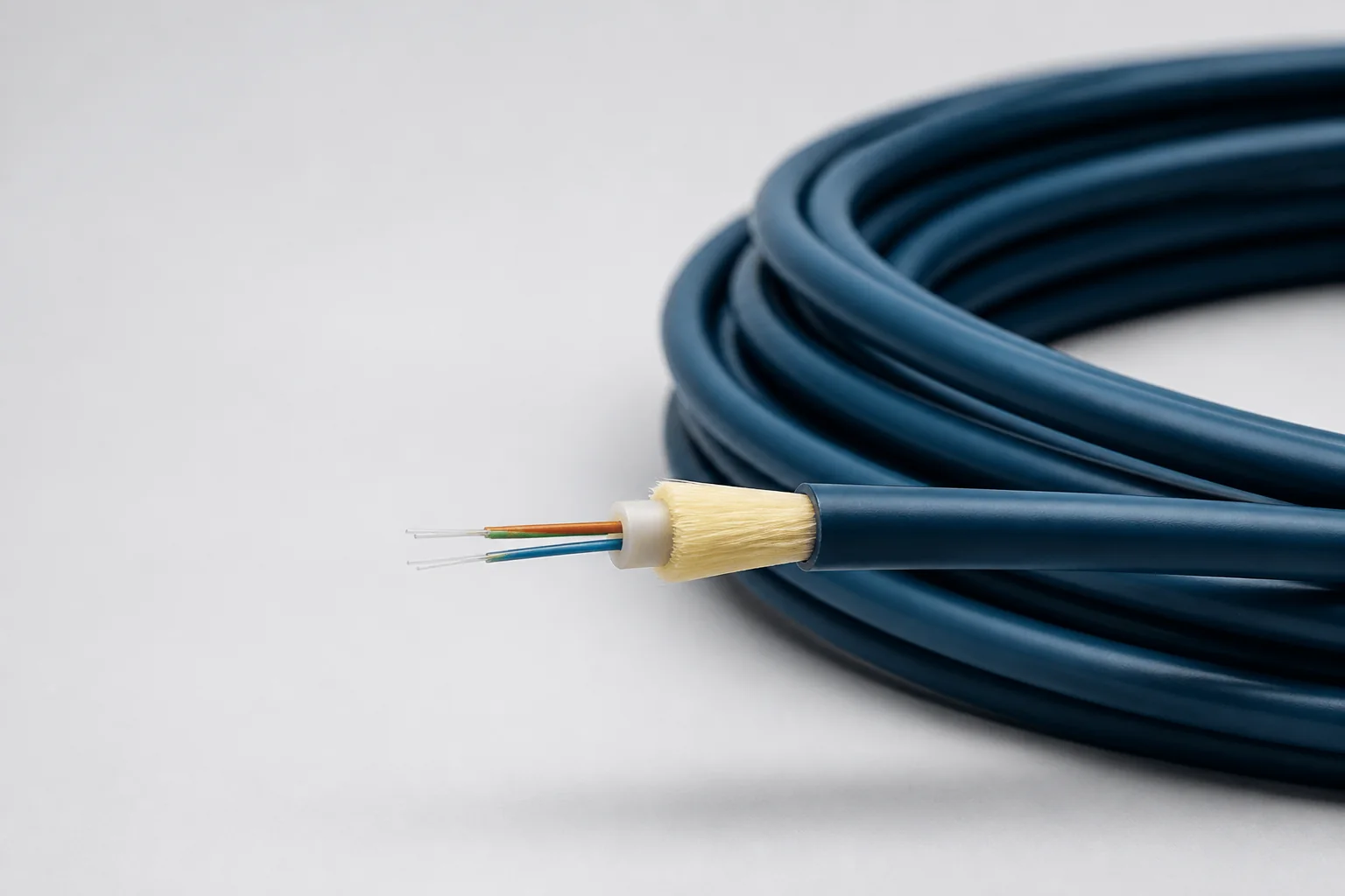
Reference configuration: Lightweight fiber-optic cable for aerospace and defense high-bandwidth interconnects, spanning singlemode and OM1–OM5 multimode directions through 100 Gb/s with PFA, FEP or PEEK jackets and buffered strength systems controlling optical loss, microbend and wide-temperature protection.
View specifications