Cat 8 / 40 Gb/s
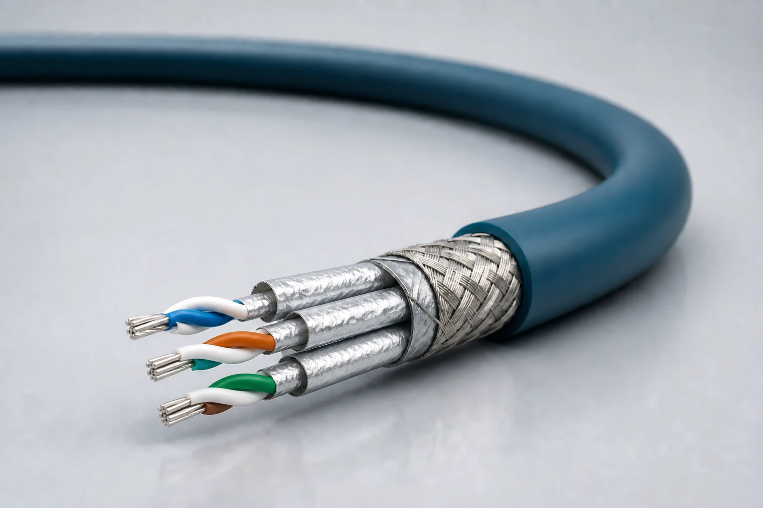
Four individually shielded pairs plus overall shield
Short high-bandwidth channel
Mission computing, radar and high-throughput equipment
Enquire about this configuration
CONMOLY / ENGINEERING & CONNECTIVITY
Reference configuration: Controlled-impedance interconnects for avionics, mission equipment, high-speed vision and precision industrial networks, spanning Cat 5e, Cat 6A and Cat 8 directions with insertion loss, return loss, crosstalk and skew managed as a complete channel.
Data Cables
CM-DATA-ETH
Ethernet Cables
Reference configurations only; specifications and certifications require confirmation.
Selection reference. Published third-party figures below describe specific reference configurations; they are not Conmoly guaranteed values or certifications. Confirm the final construction and test requirements with engineering.
Limits vary by category, gauge and part number; confirm each value against the target link configuration.
Scroll the table horizontally to view all configuration conditions.
| Parameter | Reference value | Configuration / condition |
|---|---|---|
| Maximum data rate | 40 Gb/s | Cat 8 four-pair construction |
| Maximum data rate | 10 Gb/s | Cat 5e / Cat 6A four-pair construction |
| Transmission frequency | 1 GHz | Cat 5e two-pair construction |
| Frequency & link length | 100 MHz · 70 m / 50 m | Cat 5e Quadrax; 24 AWG / 26 AWG |
| Operating temperature | −65 to +200 °C | Full configuration range |
| Diameter / MBR / weight | 6.85 mm · 13.7 mm · 49.0 g/m | Ultralight Cat 6A, 24 AWG, RCN9265-24 |
Reference source: www.gore.com
| Cat 8 four-pair | For short high-throughput equipment links up to 40 Gb/s, with pair-to-pair crosstalk, return loss and high-frequency insertion-loss budget controlled together. |
|---|---|
| Cat 6A four-pair | For avionics backbones, vision and mission networks up to 10 Gb/s, balancing transmission performance, diameter and mass. |
| Cat 5e two-pair | For two-pair protocols and space-constrained equipment links, reducing conductor count, diameter and mass while supporting frequency directions up to 1 GHz. |
| Cat 5e Quadrax | A 100-ohm symmetrical quad for aerospace connector systems; indicative link directions are 70 m for 24 AWG and 50 m for 26 AWG. |
These codes support solution discussions and requirement capture; they are not released standard part numbers. Final part number, dimensional tolerances and inspection requirements are frozen in the approved drawing and technical specification.
Four individually shielded pairs plus overall shield
Short high-bandwidth channel
Mission computing, radar and high-throughput equipment
Enquire about this configurationFour twisted pairs with lightweight jacket
Wide temperature and low mass
Avionics backbone, HD vision and equipment networks
Enquire about this configurationTwo individually shielded pairs
Compact cross-section and mass reduction
Sensors, cameras and point-to-point control links
Enquire about this configuration100-ohm symmetrical quad
70 m (24 AWG) / 50 m (26 AWG)
Circular connectors and existing Quadrax interfaces
Enquire about this configuration| Plated stranded conductors | Gauge, plating and stranding are selected for flex, strength, resistance and termination. |
|---|---|
| Low-loss insulation | Dielectric material and wall thickness control target impedance, delay and attenuation. |
| Differential pairs | Lay length, pair roundness and pair-to-pair consistency are managed. |
| Pair and overall shields | Foil, braid and drain paths are configured for crosstalk, EMI and grounding strategy. |
| Jacket and termination | Matched to temperature, flame, abrasion, marking and connector strip dimensions. |
| Protocol direction | Cat5e, Cat6A, Cat8 or project-defined link target |
|---|---|
| Pairs and topology | 2-pair, 4-pair, symmetrical quad, point-to-point or backbone |
| Link length | Cable length, connector count and allowable insertion-loss budget |
| Mechanical envelope | Diameter, mass, bend radius and routing channel |
| Environment | Temperature, vibration, abrasion, fluids, flame or vacuum |
| Termination | Circular, rectangular, modular or pigtail interface |
Protocol class, data rate and channel distance are confirmed only after validation of the final cable construction, connectors and complete channel.
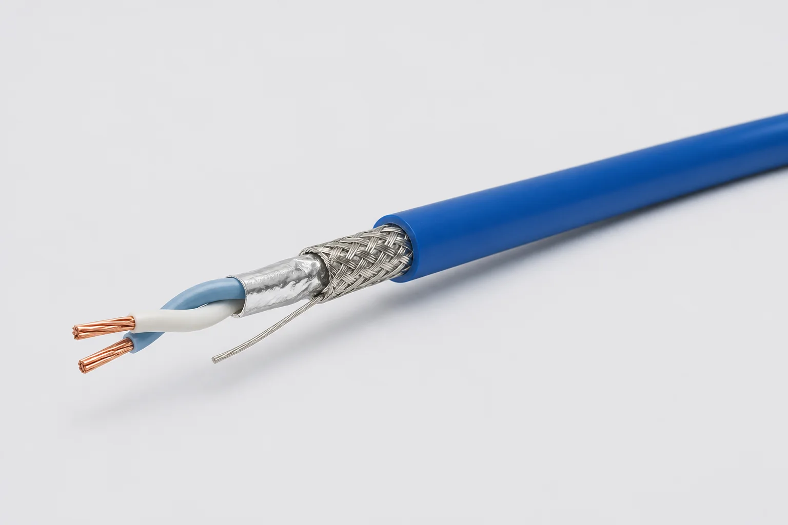
Reference configuration: 100-ohm single-pair shielded cable for aerospace, vehicle and precision-equipment differential links through 1 GHz, using controlled twist, foil, braid and drain paths to manage impedance, common-mode noise and wide-temperature reliability.
View specifications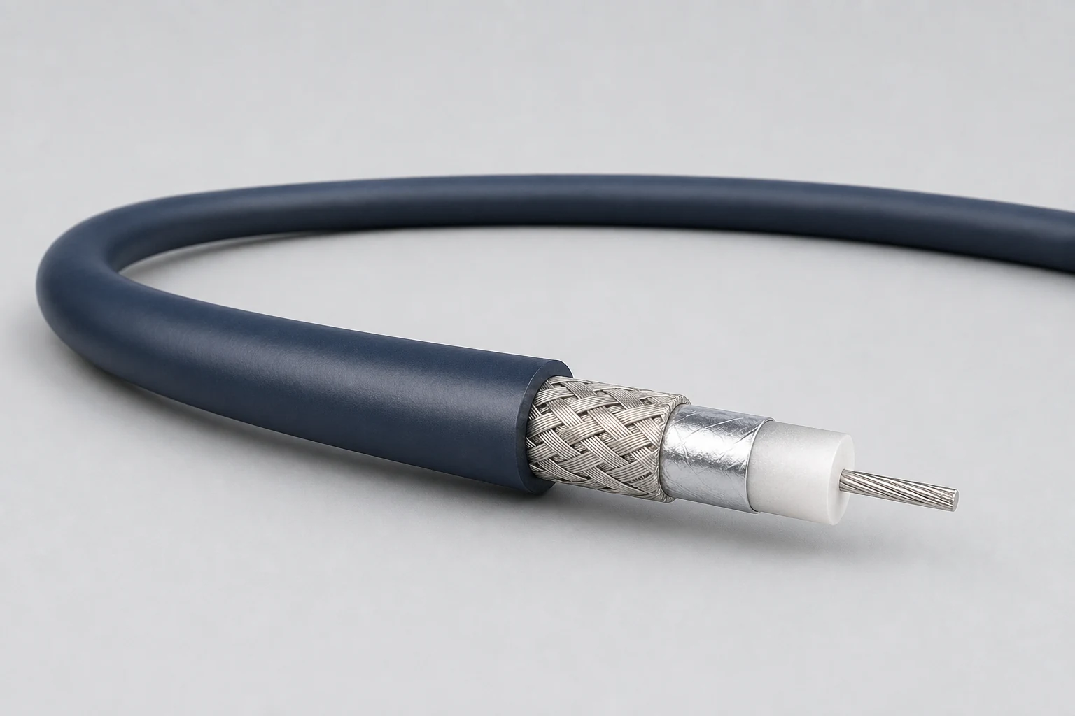
Reference configuration: Precision concentric transmission paths for video, timing, instrumentation and sensitive single-ended signals, spanning 50- and 75-ohm directions with frequency, loss, shielding and connector transitions defined as a complete assembly.
View specifications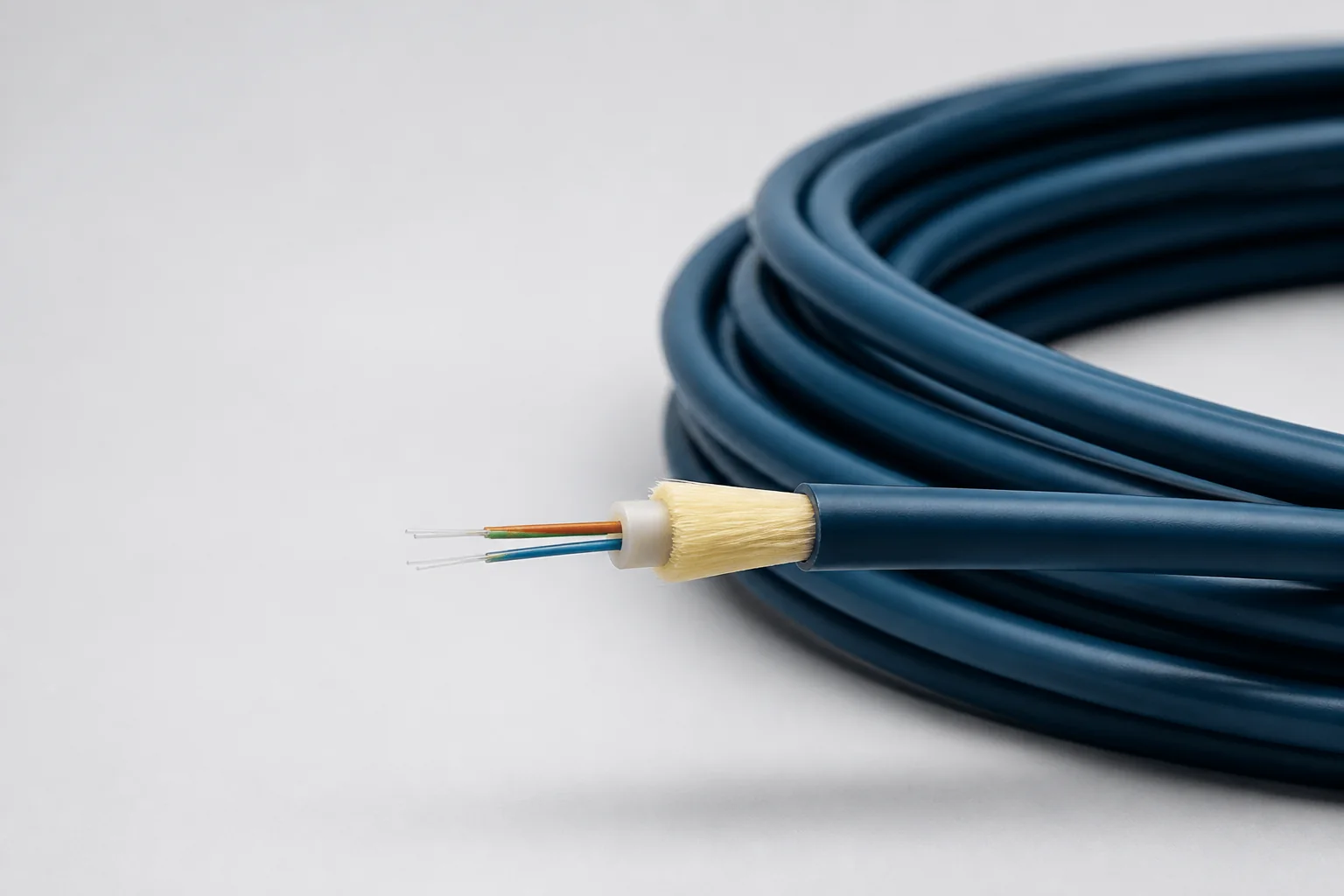
Reference configuration: Lightweight fiber-optic cable for aerospace and defense high-bandwidth interconnects, spanning singlemode and OM1–OM5 multimode directions through 100 Gb/s with PFA, FEP or PEEK jackets and buffered strength systems controlling optical loss, microbend and wide-temperature protection.
View specifications